Operation, Power consumption and power loss – d&b D6 Hardware User Manual
Page 16
5.2.
Operation
5.2.1. Power consumption and power loss
The power required from the mains supply and the waste heat
produced by the amplifiers power loss vary depending on the load
impedance and the signal levels and characteristics (e.g. speech, music).
In practice, the theoretical peak power consumption of a system will
only be sustained for a short period of time. Basing mains current and
air conditioning plant requirements on the peak power consumption of
the sound system would result in a generously over-specified
installation. The key factor in power consumption calculations is the crest
factor (CF) of the music or speech signal - the ratio of peak to
sustainable RMS voltage of the signal.
A crest factor of 2.4 represents 1/3 of the maximum sine output power
and it can be seen as the worst case signal that can be accessed in real
world conditions. A proper power distribution should be able to handle
the current ratings given in the table below referring to CF 2.4. Using
the D6 temporarily with well known signals of higher crest factor, the
power distribution can be downsized within the range given in the table.
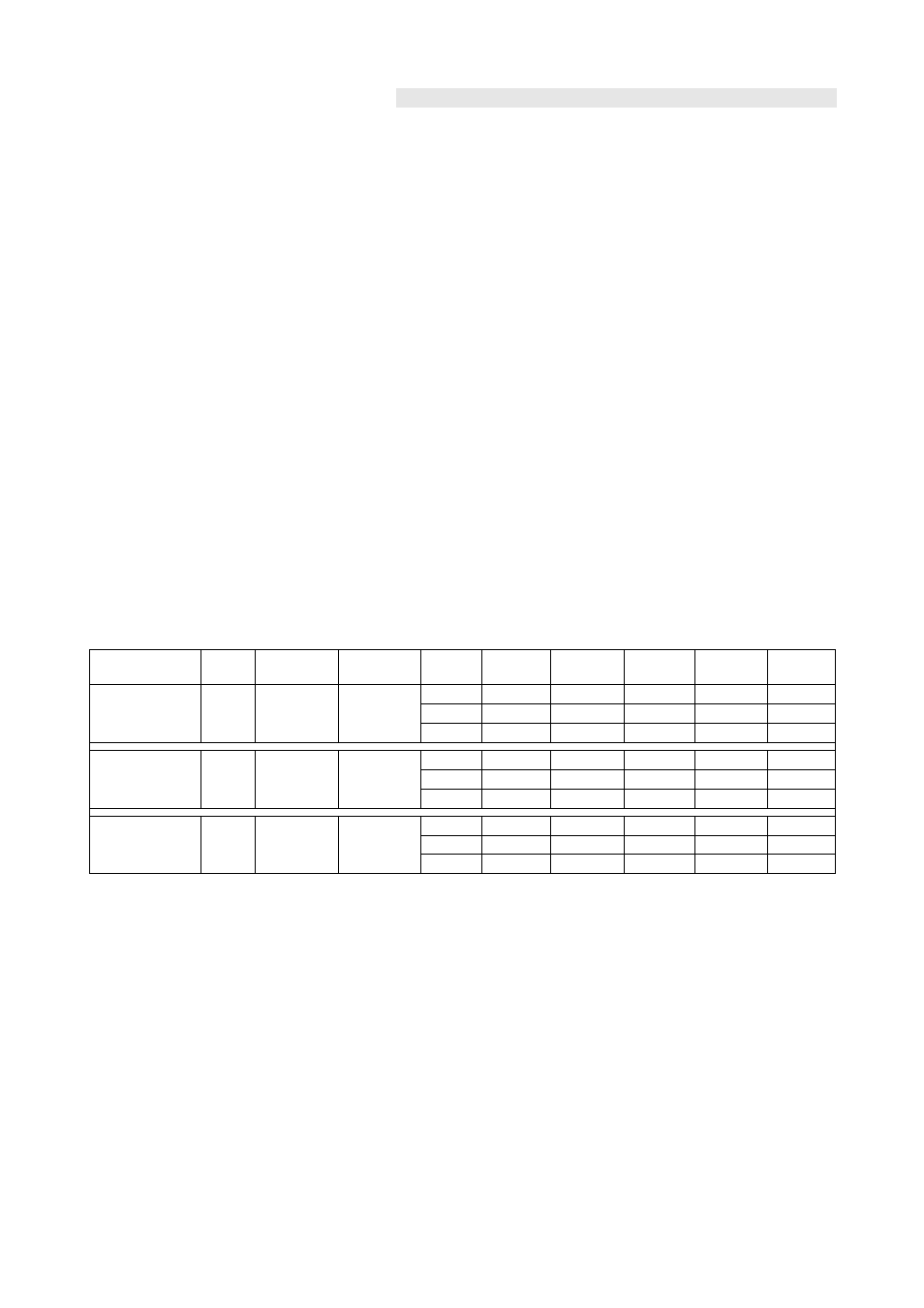
The table gives power figures for various types of signal waveforms.
They were measured on a D6 driving a 4 ohm load (both channels) to
the clipping point of both channels using a sine wave burst signal of
24 dBu with a variable duty cycle. The mains power supply used for the
measurements supplied an ideal sine wave with 230 V/50 – 60 Hz at
an internal resistance of 0.5 ohms (0.12/0.1 ohms for 115/100 V)
equivalent to a mains lead of 20 m (65.6 ft) with a cross section of
1.5 mm
2
(6 mm
2
/ 8 mm
2
for 115/100 V).
Signal
waveform
CF
Duty
P
out
[W]
P
in
[W]
P
loss
[W]
I
in
[A]
U
in
[V]
BTU/hr
kCal/hr
Sinus
1.4
1/1
1200
1560
1645
1715
360
445
515
6.8
14.3
17.2
230
1228
310
115
1518
383
100
1757
443
Highly compressed
music*
2.4
1/3
400
520
550
570
120
150
170
2.3
4.8
5.7
230
410
103
115
512
129
100
580
146
Music with low
dynamic range
4.0
1/8
150
215
220
220
65
70
70
1.0
2.0
2.2
230
222
56
115
239
60
100
239
60
Tab. 4: D6 Power balance
Key:
CF: Crest factor, Duty: Duty cycle, P
out
[W]: Max. average output power (sum of both channels), P
in
[W]: Input power (effective power)
P
loss
: Power loss (thermal power), I
in
[A]: Resulting current, U
in
[V]: Mains voltage
* Maximum practicable operation
D6 Amplifier, Hardware manual
(1.9 EN)
Page 16 of 24