Front panel – CUE relayCUE-8 User Manual
Page 5
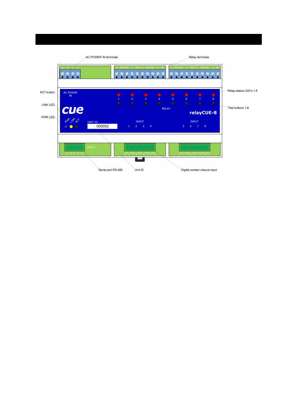
2. Front panel
On the front panel of relayCUE-8, there are the following indicators and buttons (from left to right):
•
PWR LED lighted on whenever the unit is powered.
•
LINK LED indicates activity on serial port. After power on this unit this LED flashes OK in
“Morse alphabet” - if unit power on test has not recognized any problems and the unit is ready
to work. If power on diagnostic recognizes some kind of internal failure, this LED starts flashing
regularly.
•
Relay-status LED's 1-8 - these LEDs are indicating current relay status where relay closed is
indicated by LED light on.
•
Test buttons 1-8 - under normal operation, these buttons are logically in parallel to inputs 1-8.
Pressing this button has the same effect as pressing a button connected to the appropriate
input.
•
ACT button - when this button is pressed, the relay LED indicators display the Address and
Bank parameters in binary code (for value coding see table below).
Address:
on relay LED 1-4 (where LED 1 is LSB and LED 4 is MSB)
Bank:
on relay LED 5-8 (where LED 5 is LSB and LED 8 is MSB)
Using this ACT button, you can check the actual setting of both basic system parameters
Address and Bank.
When holding the ACT button, you can also change manually the actual setting of Address
and Bank. By pressing buttons 1-8 (while instant press on ACT) you can toggle the actual
value. The new value must be confirmed by releasing the ACT button and immediate short
press of this button. The new confirmed value displayed on LEDs flashes several times for
a confirmation that the unit accepted the new value.
User Manual relayCUE-8
www.cuesystem.com
Page 5 of 24