5 wiring, Wiring, Ing to chapter 5 – Crompton Controls M10 User Manual
Page 10: D fig. 1, Chapter 5, 5wiring
8
Wiring
Emotron AB 01-2550-01r3
5
Wiring
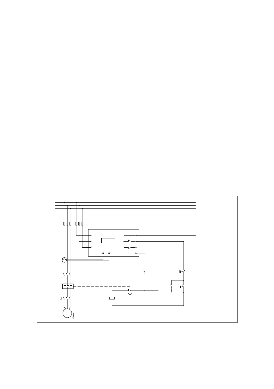
The following wiring diagram provides an example of how the Emotron M10
can be connected to control the start/stop circuit of a three-phase motor, Fig. 1,
page 8. Connections to a single-phase motor are described later in this manual
(Fig. 2).
1. The current transformer CTMXXX must be placed in the same phase that is
connected to terminal 9, phase L1, see Fig. 1. Failure to follow this require-
ment will result in the monitor failing to function.
2. For single-phase connection see Fig. 2, page 9.
Normally the appropriate current transformer (CTM XXX) will have been
ordered and shipped with the Emotron M10. Check that this is the case; see
Chapter 6 page 11 Selection of current transformer, contact the supplier if in
doubt.
When using DC voltage, terminal 6 should be connected to negative polarity
(ground) and terminal 5 to positive polarity (max. 48 VDC), see Fig. 1, page 8.
See also the alternative auxiliary circuit Fig. 11, page 29.
Fig. 1
Standard wiring 3-phase motors (alternatively see Fig. 11, page 29)
5
8
7
6
2
1
13
11
9
CTMxxx
L3
L2
L1
K1
K1
RES
S1 S2
L2
L3
L1
C
NO
NC
M10
U
V
W
M
K1
Max. 240 VAC (alt. 0 VDC-)
Stop
Start
N (alt. 48 VDC+)
Please see CTM information
on table 1, page 11 .
Note: Monitor voltage,
see note on page 9.