COMMELL MPX-24794S User Manual
Page 13
MPX-24794S User’s Guide
Ver 1.10
Taiwan Commate Computer Inc.
8
CN_GPIO1_8
CS0#
CN_GPIO1_18 I2CmSDA (4.7 K Ohm)
CN_GPIO1_9
CS1#
CN_GPIO1_19 Reserved
CN_GPIO1_10 CS2#
CN_GPIO1_20 I2CmSCL (4.7 K Ohm)
Table 1 CN_GPIO1 Pin Definitions
Note:
A pull-up 4.7 K Ohm resistor is installed on I2CmSDA line and I2CmSCL line
respectively.
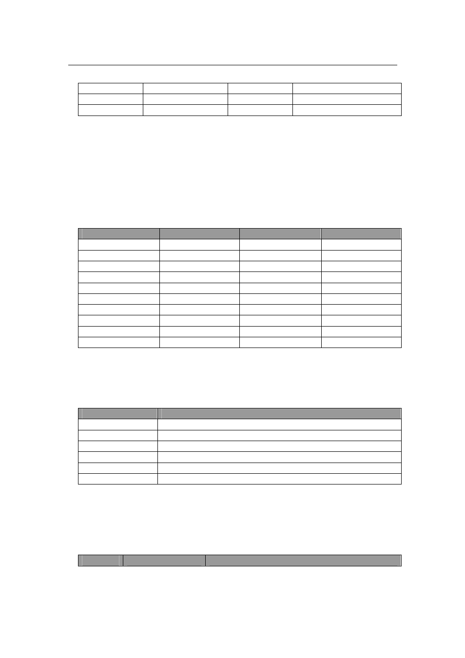
The following table shows the pin-out definitions of the CN_GPIO2 connector.
PIN
Description
PIN
Description
CN_GPIO2_1
Port_3_0
CN_GPIO2_11
Port_4_2
CN_GPIO2_2
Port_3_1
CN_GPIO2_12
Port_4_3
CN_GPIO2_3
Port_3_2
CN_GPIO2_13
Port_4_4
CN_GPIO2_4
Port_3_3
CN_GPIO2_14
Port_4_5
CN_GPIO2_5
Port_3_4
CN_GPIO2_15
Port_4_6
CN_GPIO2_6
Port_3_5
CN_GPIO2_16
Port_4_7
CN_GPIO2_7
Port_3_6
CN_GPIO2_17
N/C
CN_GPIO2_8
Port_3_7
CN_GPIO2_18
N/C
CN_GPIO2_9
Port_4_0
CN_GPIO2_19
GND
CN_GPIO2_10
Port_4_1
CN_GPIO2_20
GND
Table 2 CN_GPIO2 Pin Definitions
The following table shows the pin-out definitions of the JP1 connector.
PIN
Description
J1_1
Reserved
J1_2
Reserved
J1_3
Reserved
J1_4
Reserved
J1_5
Reserved
J1_6
Enter firmware update mode via grounding this pin
Table 3 J1 Connector pin-out definitions
The following table shows the USB portion pin-outs of the Mini-PCIe interface.
Please be noted that power pins are not showed.
Pin
Name
Description