COMMELL MPX-24794S User Manual
Page 12
MPX-24794S User’s Guide
Ver 1.10
Taiwan Commate Computer Inc.
7
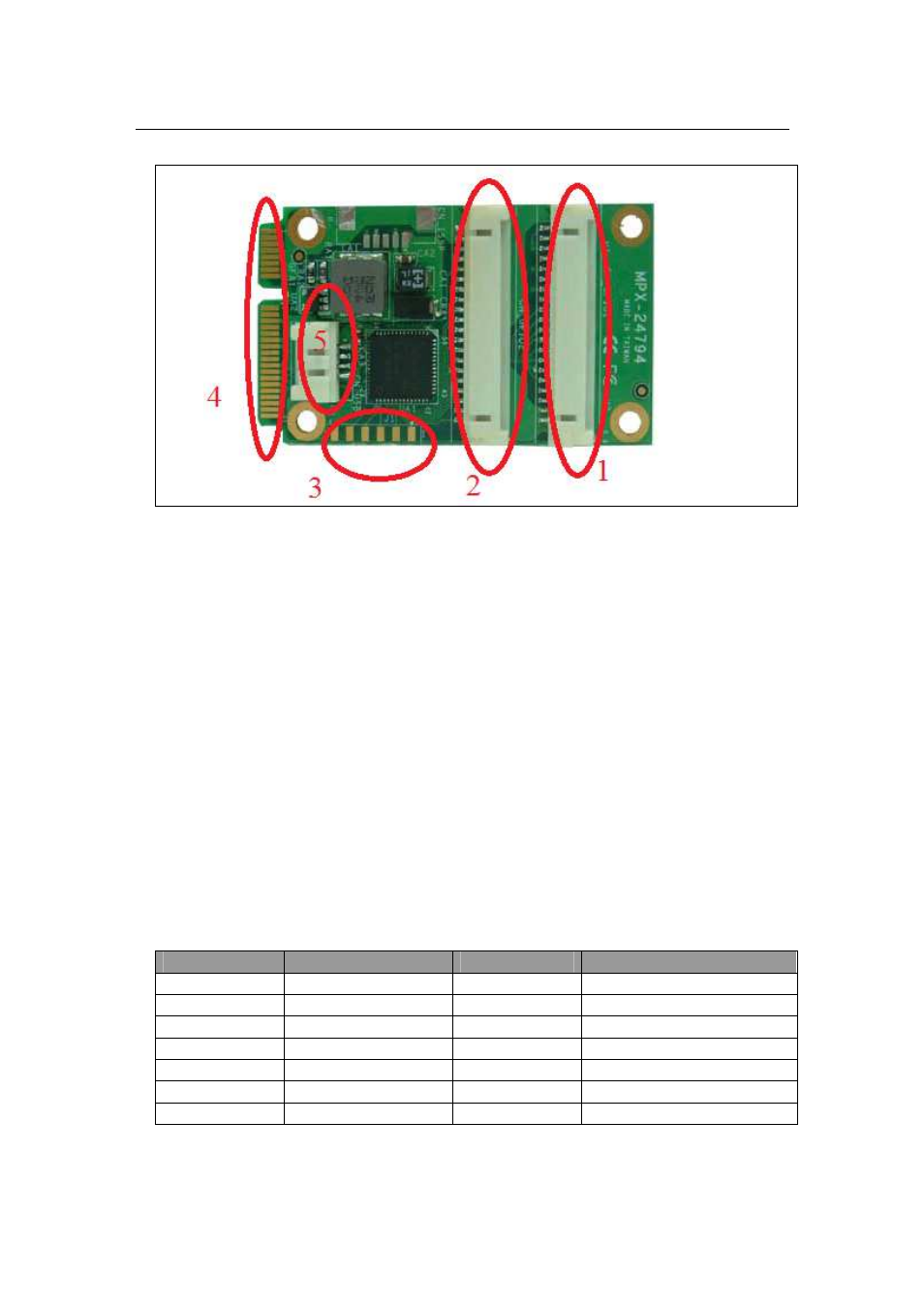
Figure 4 MPX-24794S Connectors
These five connectors are:
1. CN_GPIO1 – The connector that contains SPI master signals and SPI slaves
chip select signals, I2C master SCL and SDA signals, as well as Counter
signals.
2. CN_GPIO2 – All GPIO signals.
3. JP1 - Firmware update signals and others.
4. Mini-PCIe USB only signals – Plus this board into a Mini-PCIe slot will
connect to a USB port of your motherboard.
5. CN_USB – An alternate way to connect to a USB port of your motherboard
via connect OALUSB-H4-1 cable to this connector and its type A plug-in
connector.
The following table shows the pin-out definitions of the CN_GPIO1 connector.
PIN
Description
PIN
Description
CN_GPIO1_1
GND
CN_GPIO1_11 CS3#
CN_GPIO1_2
GND
CN_GPIO1_12 CS4#
CN_GPIO1_3
PWR+5V
CN_GPIO1_13 CNTR_EN
CN_GPIO1_4
PWR+5V
CN_GPIO1_14 CNTR_CO
CN_GPIO1_5
MOSI
CN_GPIO1_15 Reserved
CN_GPIO1_6
MISO
CN_GPIO1_16 CNTR_TO
CN_GPIO1_7
SCLK
CN_GPIO1_17 Reserved