Warning, Check all sensor wiring before applying power, 3 wire preparation and insertion – Casella CEL Automatic weather station User Manual
Page 13
WARNING
Check all sensor wiring before applying power.
Systems incorporating extension cables and junction boxes may use an
intermediate multicore colour-coded cable. Details of such non-standard wiring
can be found in the “Calibration & System Details” section of this handbook.
The sensor connections are made via a series of plugs incorporating
push release type terminals as described in Section 2.5.3.
Each sensor wire should be connected to the appropriate terminal of its
plug according to the Wiring Diagram.
The logger channel number asigned to each sensor is detailed in the
“Calibration & System Details” section of this handbook.
2.6.3
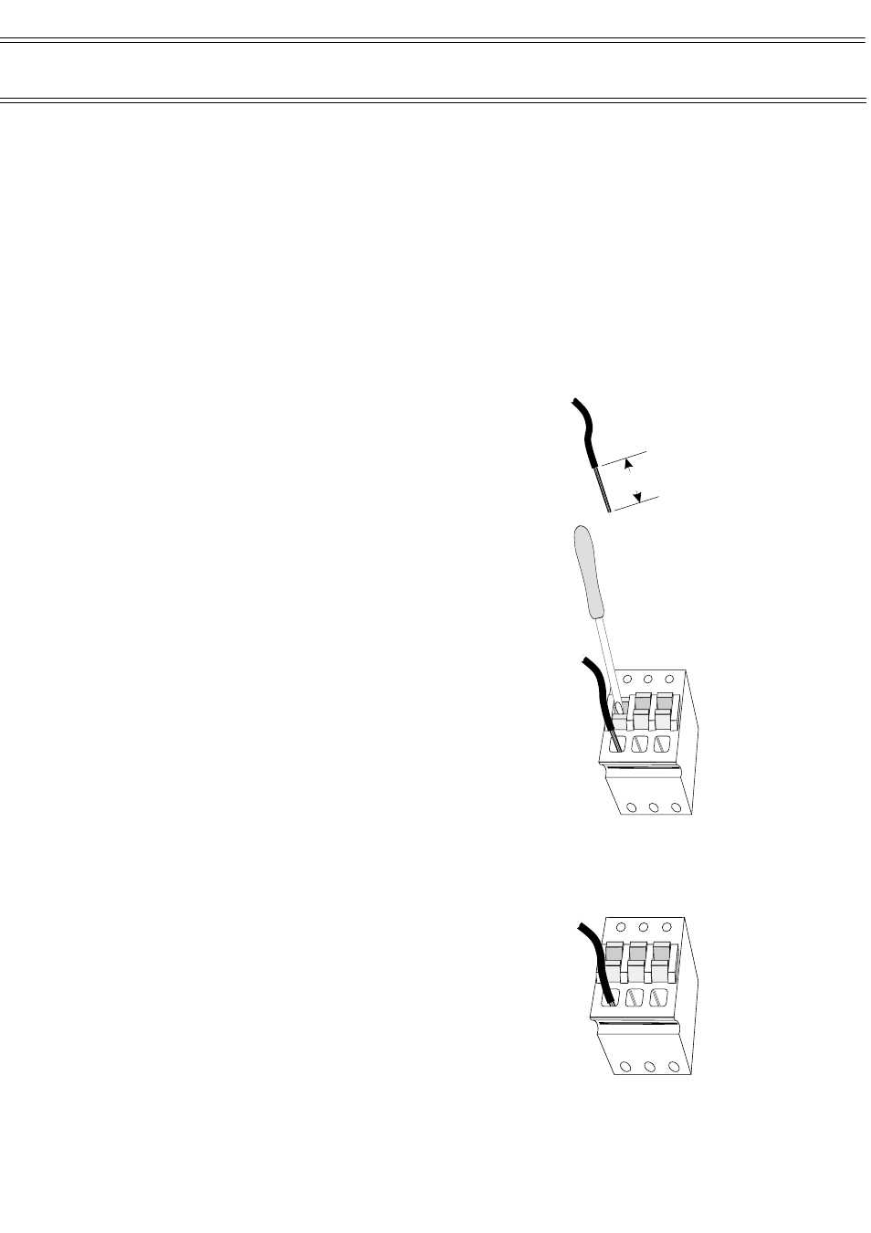
Wire Preparation and Insertion
To insert a wire into a spring terminal, first strip
back the insulation leaving 10 mm of bare wire
exposed as shown.
Use a small flat headed screwdriver (or
similar) to fully depress the orange plunger
located above the hole into which the wire is to be
inserted. Then insert the wire into the hole as far
as it will go, as shown.
Release the orange plunger and the wire
is held captive by the connector as shown.
A gentle tug on the wire will confirm that
it is held firmly.
Stripped
Conductor
i
01083
10 mm
Use a small
screwdriver to
depress the
orange clamp
while inserting
the stripped
end of the
conductor
i
ii
iii
iiii
iiiii
iiiiii
iiiiiii
01084
Remove the
screwdriver to
release the
clamp and
grip the
conductor
i
ii
iii
iiii
iiiii
01085
Page 13 of 34
Automatic Weather Station
Assembly & Commissioning Handbook