Casella CEL CEL-160 User Manual
Page 8
followed by a C. (Operation of C key is actual
entry time, eg for 5.53 p.m. key 1753C). Start
up state 00H00M00S. The instrument also has
a 10 day elapsed day counter and this will
increment 1 day as the clock passes 24.00 but
it cannot be preset.
D Preset Scale Annotation
When the instrument is being used with the
integral sound level meter, the annotation on
the top of the paper is the main attenuator
setting whilst that at the bottom is the same
level minus the dynamic range setting. If it is
required to operate in the non SLM mode then
the FSD figure should be entered as a one or
two digit decade followed by D. The minimum
scale deflection will again, be calculated from
the dynamic range setting.
eg for 180 dB FSD key 180D. Start up state
SLM calibration.
E Frequency Analysis Trigger
Operation of this key will initiate the frequency
analysis program. Full details are given in
Section 6 of this manual.
F. Select Frequency Analyser Type
The control logic to operate the following
analysers is pre-programmed into the CEL-160,
however, non-standard packages are available
and if fitted to this unit details are given in
section 12 of this manual.
0 CEL-196 Automatic Third Octave 20 Hz- 20 kHz
1 Rion SA-59 Serial Third Octave 25 Hz-20 kHz
2 Rion SA-59 Serial Third Octave 2.5 Hz-2 kHz 3 Bruel
and Kjaer 1618 Serial Third Octave
4 Bruel and Kjaer 2215 Serial Octave
5 Bruel and Kjaer 1616 Third Octave 25 Hz-40 kHz
6 Bruel and Kjaer 1621 Continually Variable Narrow
Band 20 Hz-20 kHz
7 Bruel and Kjaer 1621 Continually Variable Narrow
Band 2 Hz-2 kHz
8 Rion SA-24 Real Time Third Octave 31.5 Hz-8 kHz
9 Rion SA-24 Real Time Third Octave 1 Hz-250 Hz
eg for Bruel and Kjaer 1616 key 5F. Start up
state 0F.
3.2
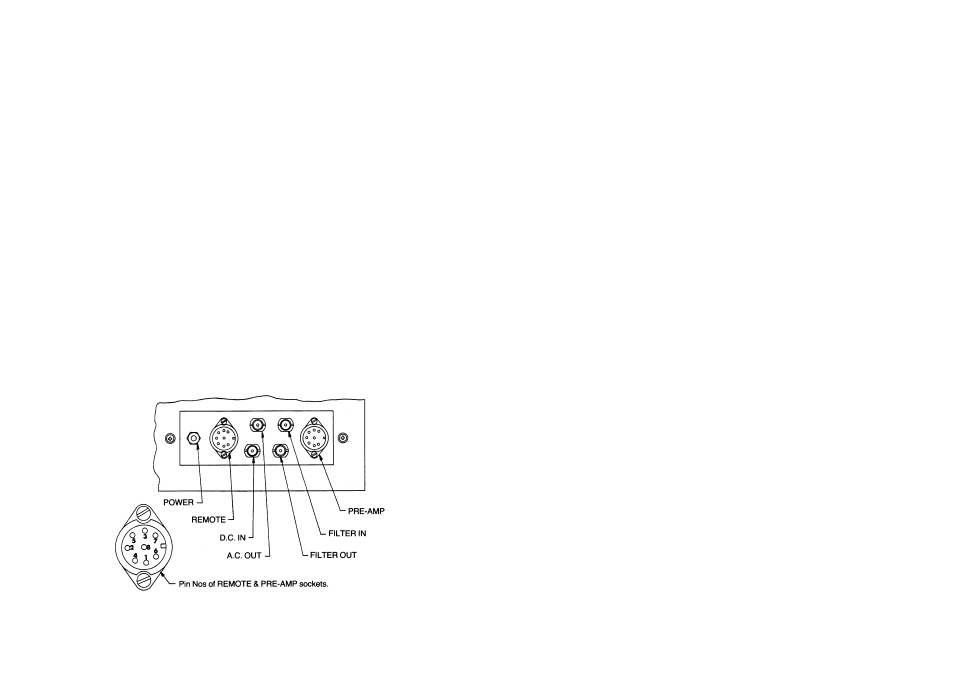
Connectors
All the input connections to the CEL-160 are
on the panel that is located on the right hand
side of the instrument. The functions of these
are as below and are shown in Fig 1.
PRE-AMP: This socket accepts the input from
the CEL-2980 preamplifier which should be
connected via the CEL-3686/2 cable. It may
also be used for direct AC inputs. Full details of
connections and loading conditions are given in
Figure 2. It must be noted that when direct AC
inputs are connected, the function of the main
range switch is different; reference should be
made to Section 4.3 for full details.
FILTER IN AND FILTER OUT: These are
primarily intended for the connection of
external frequency analysers such as the
CEL-196. The filter output connector is only in
circuit when the frequency weighting (LIN - A-
FILTER) is set to the filter position, however,
the filter input is always in circuit.
Figure 1: Connector locations and pin connections
Page 8 - CEL-160 Graphic Recorder