Applied Motion SVAC3-IP-E120 User Manual
Svac3 quick setup guide, Requirements, Step 1
SV
SVAC3 Quick Setup Guide
Requirements
▪
A compatible servo motor.
▪
A small flat blade screwdriver for tightening the connectors (included).
▪
A personal computer running Microsoft Windows 98, NT, Me, 2000, XP, Vista, or 7.
▪
Quick Tuner™ software (version 2.2.17 or later) available at www.applied-motion.com/products/software.
▪
For Q models, Q Programmer software (available at www.applied-motion.com).
▪
A CAT5 network cable (not included).
▪
For more detailed information, please download and read the SVAC3 Hardware Manual, available at www.applied-motion.com/support/manuals.
To begin, make sure you have the following equipment:
Step 1
a)
Download and install the Quick Tuner™ and, for -Q models, the Q Programmer™ software.
b)
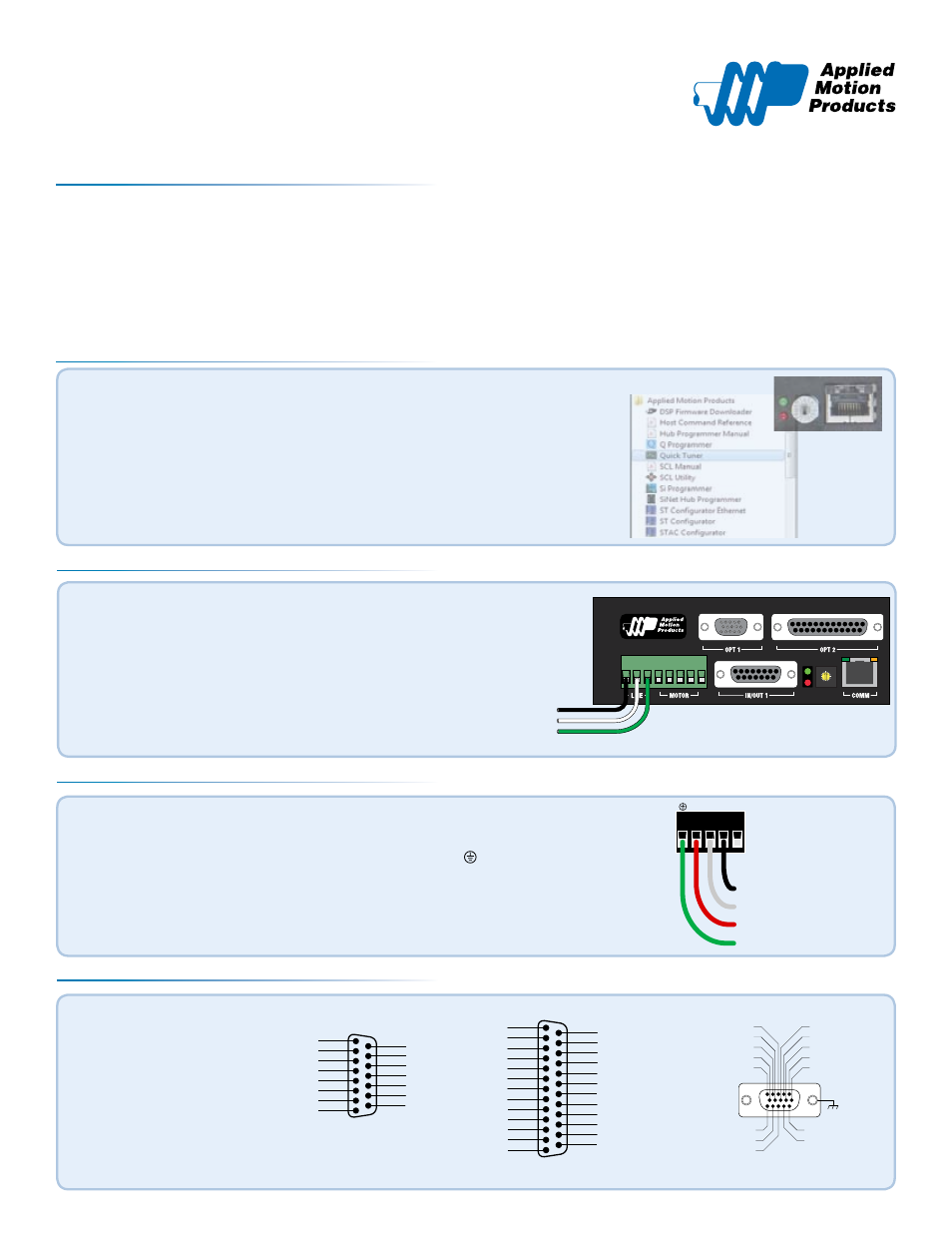
Launch the software by clicking:
Start / Programs / Applied Motion Products / Quick Tuner
c)
Connect the drive to your network or PC using a standard CAT5 cable.
d)
Select an appropriate IP address using the rotary switch on the SVAC3. For more information
about network configurations and IP addressing, please consult the SVAC3 Hardware Manual.
Step 2
Wire the drive to the AC power source.
(do not apply power until all connections to the drive have been made)
Note, the SVAC3-120 accepts AC voltages from 108-132 VAC,
while the SVAC3-220 accepts AC voltages from 108-242 VAC.
The SVAC3-120 contains an internal 8A fast acting fuse. The SVAC3-220
contains an internal 3.5A fast acting fuse. If an external fuse is desired,
we recommend a 6A fast acting fuse for the 120V SVAC3 and a 3 amp
fast acting fuse for the 220V version.
4
3
21
0 F
E D C B A
9 8
76
5
To Line (Hot)
To Neutral
To Earth Ground
Step 3
Connect the drive to the motor. If you are using one of the recomended Applied Motion motors, connect the
motor as shown.
Be sure to connect the motor case ground to the SVAC3 ground terminal.
For a non-Applied Motion Products motor, please refer to your motor specs for wiring information.
To Motor Case
Motor C (or W) phase
Motor B (or V) phase
Motor A (or U) phase
A
B
C NC
a)
Connect the I/O
b)
Connect the Encoder. For
Applied Motion motors we
recommend using standard
encoder extension cables
(BLUENC type for M series
motors, 3004-230 type for
V series motors) to connect
the motor’s encoder and Hall
signals to the drive.
Step 4
encoder Z+ (5)
Hall 1-(10)
encoder B- (4)
Hall 1+ (9)
encoder B+ (3)
Hall 3+ (13)
Hall 3- (14)
GND (15)
(12) Hall 2-
(11) Hall 2+
(6) encoder Z-
(1) encoder A+
(7) +5VDC 200mA
(2) encoder A-
(8) GND
Front View
ENCODER
X4+
X4-
Y1/FAULT+
Y1/FAULT-
Y2+
Y2-
ANALOG IN
X1/STEP+
X1/STEP-
X2/DIR+
X2/DIR-
X3/EN+
X3/EN-
GND
+5V OUT
100mA MAX
1
2
3
4
5
6
7
8
9
10
11
12
13
14
15
IN/OUT 1
This connector is included
on all models.
OUT1+
OUT2+
OUT3+
OUTCOM
+5V OUT, 100mA MAX
GND
OUT4+
OUT4-
IN7+
IN7-
IN8+
IN8-
N/C
N/C
N/C
IN6
IN5
IN4
IN3
INCOM
IN2-
IN2+
IN1-
IN1+
GND
1
2
3
4
5
6
7
8
9
10
11
12
13
14
15
16
17
18
19
20
21
22
23
24
25
IN/OUT 2
This connector is included on
-Q, -IP models.
920-0052 rev A