Step 3, 4 wire rs-485 – Applied Motion STM23Q-2RE User Manual
Page 2
Step 3
If you have any questions or comments, please call Applied Motion Products Customer Support:
(800) 525-1609, or visit us online at www.applied-motion.com.
404 Westridge Dr.
Watsonville, CA 95076
Tel: 800-525-1609
Fax: 831-761 -6544
www.applied-motion.com
a)
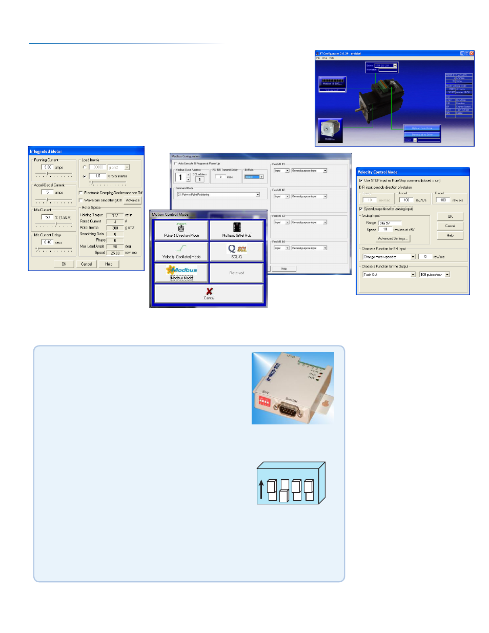
Apply power to the drive. The drive model and firmware revision should be
automatically displayed. If they are not, check the com port setting.
b)
Follow the configuration instructions in the ST Configurator™ help screens.
The ST Configurator™ software can be used to set up your drive to operate in
several different modes including: Pulse & Direction, Analog Velocity,
and SCL.
c)
ST Configurator™ includes a self test option (under the Drive menu) to
verify that the STM and power supply are correctly wired and configured.
920-0020 E
STM23/24 Quick Setup Guide
Recommended RS-485 Adapter
USB-COMi-M (P/N 8500-003)
▪
Available from Applied Motion Products
▪
Converts RS-422 and RS-485 to USB
For four wire RS-485, set SW2 to OFF and SW1,3,4 to ON.
On the USB-COMi-M screw terminal connector:
▪
Connect pin 1 to RX-
▪
Connect pin 2 to RX+
▪
Connect pin 3 to TX+
▪
Connect pin 4 to TX-
▪
Connect pin 6 to GND
▪
The DB-9 connector is not used.
Remove the two screws on the sides of the unit, then
remove the outer cover.
▪
For RS-485 operation, ensure that the row of colored pin
jumpers are installed.
1
ON
2 3 4
4 Wire
RS-485