Applied Motion STM17R-3ND User Manual
Stm17r quick setup guide, Requirements, Step 1
STM
STM17R Quick Setup Guide
Requirements
▪
A small flat blade screwdriver for configuring the DIP switches (included).
▪
DC Power Source, 12-48VDC
▪
For more detailed information, please download and read the STM17R Hardware Manual, available at www.applied-motion.com/support/manuals.
To begin, make sure you have the following equipment:
Step 1
Connect the drive to the DC power source. The STM17R will accept DC
power from 12-48VDC.
Per the diagram at the right, connect the red wire to the positive output
terminal on the power supply, typically marked V+, and the black wire to
the negative terminal, typically marked V-.
(Do not apply power until all connections to the drive have been made)
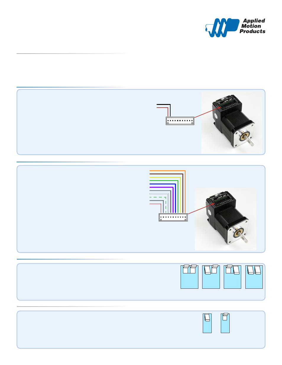
Step 2
Connect input signals to the drive. STEP and
DIR are required, EN and OUT are optional.
▪
See the STM17R Hardware Manual for circuit
connection details and examples.
STEP+
STEP-
DIR+
DIR-
EN+
EN-
OUT+
OUT
-
N.C.
V-
V+
V+
V-
STEP+
STEP-
DIR+
DIR-
EN+
EN-
OUT+
OUT
-
N.C.
V-
V+
V+
V-
NC
OUT-
OUT+
EN-
EN+
DIR-
DIR+
STEP-
STEP+
Set the motor’s idle current using switch 3.
▪
This is the percentage of running current that the motor will use when
the shaft is not rotating. Choose 90% for maximum holding torque or 50%
to reduce motor heating.
Step 4
3
50%
3
90%
Set the motor’s running current using switches 1 and 2.
▪
This is the percentage of full current that the motor will use when the shaft
is rotating.
Step 3
1 2
100%
1 2
90%
1 2
70%
1 2
50%
920-0055 rev B