Step 3, Step 5, Step 4 – Applied Motion ST10-Si-NE User Manual
Page 2: St5/10-si quick setup guide, B) connect the encoder (optional)
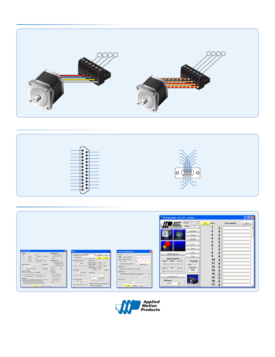
Step 3
If you have any questions or comments, please call
Applied Motion Products Customer Support:
(800) 525-1609, or visit us online:
www.applied-motion.com.
404 Westridge Dr.
Watsonville, CA 95076
Tel: 800-525-1609
Fax: 831-761 -6544
www.applied-motion.com
a)
Apply power to the drive.
b)
The Si Programmer™ software can be used to configure and
program the drive for operation. Once an Si program has been
constructed and downloaded to the drive, the program can be
executed stand-alone at power-up or from an external trigger.
Step 5
redblue
yellow
white
A+ A- B+ B-
orange+blk/wht
blac
k+org/wht
red+y
el/wht
yello
w+red/wht
A+ A- B+ B-
Figure 2
Figure 1
ST5/10-Si Quick Setup Guide
920-0008 C
Connect the drive to the motor. Four lead motors can be connected in only one way, as shown in Figure 1.
We recommend that eight lead motors be connected in parallel, as shown in Figure 2.
If using a non-Applied Motion Products motor, please refer to your motor specs for wiring information.
a)
Connect the I/O
Step 4
X COMMON
X3 / Enable
X5 / CW JOG
X4 / Alarm Reset
Analog IN
Analog IN
X2 / DIR -
X2 / DIR +
X1 / STEP+
X1 / STEP -
GND
GND
X8/CCW LIMIT -
X8/CCW LIMIT+
X7/CW LIMIT -
X7/CW LIMIT+
Y4 -
Y4+
+5V OUT
Y COMMON
Y3 / FAULT
Y2 / MOTION
Y1 / BRAKE
18
17
16
15
14
13
12
11
10
9
8
7
6
5
4
2
3
1
19
20
21
22
23
24
25
X6 / CCW JOG
IN/OUT - ST5/10 - Q/Si
Z+ (5)
NC (10)
B- (4)
NC (9)
B+ (3)
NC (13)
NC (14)
NC (15)
(12) NC
(11) NC
(6) Z-
(1) A+
(7) +5VDC 200mA
(2) A-
(8) GND
PC GND
PC TX-/RX- or B
PC TX+/RX+ or A
+RX- +TX- GND
Drive 1
Drive 2
Drive 3
+RX- +TX- GND +RX- +TX- GND
PC GND
PC RX-
PC RX+
PC TX-
PC TX+
+RX- +TX- GND
Drive 1
Drive 2
Drive 3
+RX- +TX- GND +RX- +TX- GND
b)
Connect the Encoder (optional)