Step 3, Step 4, St5/10-s quick setup guide – Applied Motion ST10-S User Manual
Page 2
Warning - If you are using a non-Applied Motion motor, do not connect the motor un-
til after you have configured the drive for your motor. Refer to Step 4.
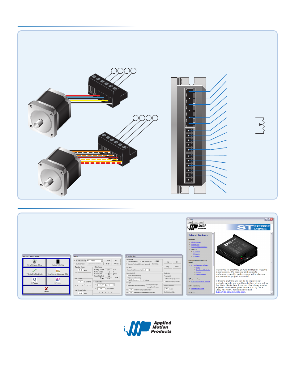
Connect the drive to the motor. Four lead motors can be connected in only one way, as shown in Figure 1.
We recommend that eight lead motors be connected in parallel, as shown in Figure 2.
If using a non-Applied Motion Products motor, please refer to your motor specs for wiring information.
Step 3
redblue
yellow
white
A+ A- B+ B-
orange+blk/wht
blac
k+org/wht
red+y
el/wht
yello
w+red/wht
A+ A- B+ B-
GND
V+ Power Supply
EN-
V- Power Supply
EN+
Motor A+
Motor A-
Motor B+
Motor B-
DIR-
AIN
DIR+
+5V
STEP-
OUT-
STEP+
OUT+
I/O Pinout - ST5/10-S
If you have any questions or comments, please call Applied Motion Products Customer Support:
(800) 525-1609, or visit us online at www.applied-motion.com.
404 Westridge Dr.
Watsonville, CA 95076
Tel: 800-525-1609
Fax: 831-761 -6544
www.applied-motion.com
a. Apply power to the drive.
b. Follow the configuration instructions in the ST Configurator™ help screens.
The ST Configurator™ software can be used to set up your drive to operate in
several different modes including: Pulse & Direction, Analog Velocity,
and SCL.
Step 4
Figure 1
Figure 2
920-0001 F
ST5/10-S Quick Setup Guide