Using the oscillator, Hi lo ➜ bypass int ➜ ➜ ext – Applied Motion PDO2035 User Manual
Page 10
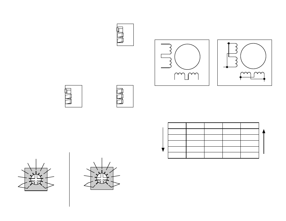
Using the Oscillator
The PDO2035 is equipped with an internal pulse
generator that you can use to control the motor. To
select the oscillator mode of operation (run/stop mode)
move switch 2 away from the
BYPASS label, as shown
at the right.
The oscillator is activated by driving the
STEP input low. The frequency of step
pulses will increase linearly, accelerating the motor until it reaches a preset slew
speed. The motor will remain at this speed until the
STEP input is driven high. The
step pulse frequency then decreases linearly, decelerating the motor and load to
rest. The PDO2035 lets you choose from two oscillator speed ranges: 10 - 1200
steps/second (LO) and 100 - 12000 steps/sec (HI). Set the speed range with the
"LO/HI" switch.
3362
20,000
steps/sec
2
10,000
steps/sec
2
5000 steps/sec
2
2500 steps/sec
2
1200 steps/sec
2
600
steps/sec
2
300
steps/sec
2
150
steps/sec
2
(no ramp)
To adjust the speed, locate the trimpot labeled
SPEED . By turning the brass screw
you can raise or lower the speed within the range you have selected. Turning the
screw clockwise makes the motor run faster.
The acceleration and deceleration rates can also be adjusted using the trimpots
labeled
ACCEL and DECEL. The range of accel and decel rates is illustrated below.
Turning the screw clockwise makes the motor accelerate or decelerate faster.
123
HI
LO
➜
BYPASS
INT
➜
➜
EXT
➜
➜
123
HI
LO
➜
BYPASS
INT
➜
➜
EXT
➜
➜
123
HI
LO
➜
BYPASS
INT
➜
➜
EXT
➜
➜
10 - 1200 steps/sec
100 - 12000 steps/sec
A+
A–
B+
B–
8
lead
motor
8 Leads Series Connected
Eight lead motors can also be connected in two ways: series and parallel. As
with six lead motors, series operation gives you more torque at low speeds and less
torque at high speeds. In series operation, the motor should be operated at 30%
less than the rated current to prevent over heating. The wiring diagrams for eight
lead motors are shown below.
8 Leads Parallel Connected
A+
A–
B+
B–
8
lead
motor
Orange
Org/Wht
Blk/Wht
Black
Red
Red/
Wht
Yel/
Wht
Yellow
Orange
Org/
Wht
Blk/Wht
Black
Red
Red/Wht
Yel/
Wht
Yel
low
Step
A+
A-
B+
B-
0
+
–
+
–
1
–
+
+
–
2
–
+
–
+
3
+
–
–
+
4
+
–
+
–
DIR=1
cw
DIR=0
ccw
Step 3 is the Power Up State
Step Table
(full stepping)
-7-
-10-
200,000
steps/sec
2
100,000
steps/sec
2
50,000 steps/sec
2
25,000 steps/sec
2
12000 steps/sec
2
6000
steps/sec
2
3000
steps/sec
2
1500
steps/sec
2
(no ramp)
LO range accel/decel settings
Shown at 2500 steps/sec
2
HI range accel/decel settings
Shown at 25,000 steps/sec
2
3362
(speed range)
(internal oscillator)
(potentiometer)