Applied Motion 1030 User Manual
Page 4
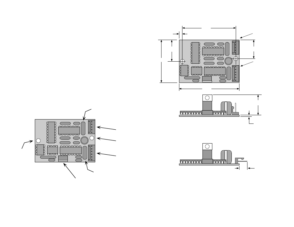
current sensing resistor
current sensing resistor
connector
motor
mounting
hole
(.156")
mounting
hole
(.156")
connector
power
step
direction
voltage regulator
(Beware, this part gets HOT!!!)
-4-
-13-
Mechanical Outline
Getting Started
To use your Applied Motion Products motor control, you will need the following:
• a 12-30 volt DC power supply for the motor. Please read the section
Choosing a Power Supply for help in choosing the right power supply.
• a source of step & direction signals (indexer, oscillator or PLC).
• a source of power to activate the optoisolation circuits. Many indexers & PLCs
have power available for this purpose. If not, you may need a small 5 - 24 VDC
power supply.
• mating connectors (see page 14)
• plastic spacers or stand-offs for mounting (see page 12)
The sketch below shows where to find the important connection and mounting
points. Please examine it now.
0.770 MAX
0.062
.300
2.00
2.25
1.60
0.80
0.70
0.125
pin 1
motor connector
pin 1
logic & power
connector
with vertical headers
with horizontal headers