Connections, Installation, Configuration – ABUS Technologies Temp DM WM Temperature Transmitter User Manual
Page 7
ABUS TECHNOLOGIES INC.
7
Temp DM-
WM
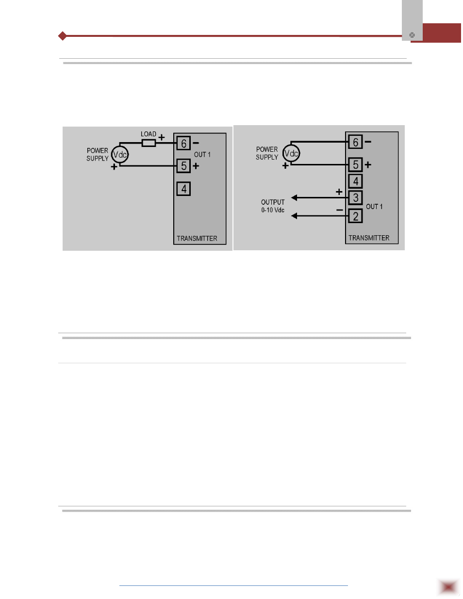
5. CONNECTIONS
The transmitter can be ordered as 4-20 mA current output or 0 to 10 Vdc
voltage output. The output signal is defined on purchase and cannot be later changed.
The figure below shows the require connections:
Electrical Connections for Temp DM/WM
LOAD represents the output signal measurement equipment (controller,
register, etc). The connection wires go inside the transmitter through to the cable gland
mounted in the transmitter case.
6. INSTALLATION
Recommendation
Conductors of small electrical signals must be distant from activation or high-
tension/current conductors, preferably passing through grounded conduits.
A specific electrical power supply network should be provided for instruments use
only.
In controlling and monitoring applications, possible consequences of any system
failure must be considered in advance.
RC filters (47 R and 100 nF, serial) in inductor charges (contactors, solenoids, etc.)
are recommended.
7. CONFIGURATION
If the default configuration or the ordered configuration satisfies the application,
then no further configuration is necessary and the transmitter is ready to be used. If a
new setting is desired, this can be accomplished by the ATxConfig and sent to the
transmitter through the ATxConfig interface.