Installation, 1 input signal, 2 function keys and lamps – ABUS Technologies A4000 Series Universal Controller User Manual
Page 7
ABUS TECHNOLOGIES INC.
7
A4000
6. INSTALLATION
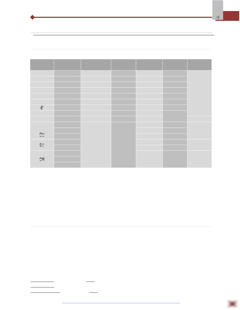
6.1 Input Signal
SIGNAL
SELECTING
SIGNAL TYPE
RANGE
RESOLUTION
ACCURACY
INPUT
IMPEDANCE
FACTORY
SETTING
B
T/C b
600 ~ 1700°C
1°C
0.5%
>100K
Yes
5
T/C S
0 ~ 1700°C
1°C
0.5%
>100K
R
T/C R
500 ~ 1600°C
1°C
0.5%
>100K
T
T/C T
0.0 ~ 400.0°C
0.1°C
0.5%
>100K
E
T/C E
0 ~ 1000°C
1°C
0.5%
>100K
J
T/C J
0 ~ 1000°C
1°C
0.5%
>100K
T/C K
0 ~ 1200°C
1°C
0.5%
>100K
Pt
T/C
-200 ~ 600°C
0.1°C
0.5%
0.2mA
Cu50/Cu100
Cu50/Cu100
-50.0 ~ 150°C
0.1°C
0.5%
Back
Ln
or
0 ~ 400 Ω
-1999 ~ 9999
12bit A/D
0.5%
0.2mA
0-50mV
-20 ~ 100mV
0.5%
>100K
0-1V
0.5%
>20K
0-5V
0.5%
>100K
0-10V
0-10V
0.5%
>200K
0-10mA
0.5%
<102Ω
4-20mA
0-20mA
4-20mA
Note:
1.
The resolution of R/S/B is 1°C; Resolution of the other signals is 0.1 in case the display is value less than 400. In case the
display value more than 400, the resolution is 1°C, over range display or negative display can also be specified at the time of
order..
2.
Pulse: Square wave, triangle wave, sine wave (need to mention when order), rating more than 4V or less than IV. Frequency
Range: 0-60KHz.
6.2 Function Keys and Lamps
6.2.1 KEYS
A: SET: Set Key
B: ▲/▼: Increase/Decrease Key
C: SET+▲: Hold the set key, press ▲ will shift digit.
D: LED flashes, press SET key to confirm Parameter.
E: The digit shifts to another one to be modified.
6.2.2 LAMPS
SV red lamp On: Indicate the set value; Flash: Indicate the external setting input value (the second input value of loop 2).
MV red lamp On: Indicate control output value. In case it is manual manipulation, it indicate the manipulate.
MAN green lamp On: Manual manipulate; Flash: In the case of auto-tune; Off: automatism.