ABUS Technologies A4000 Series Universal Controller User Manual
Page 12
ABUS TECHNOLOGIES INC.
12
A4000
7.4 Additional Notes
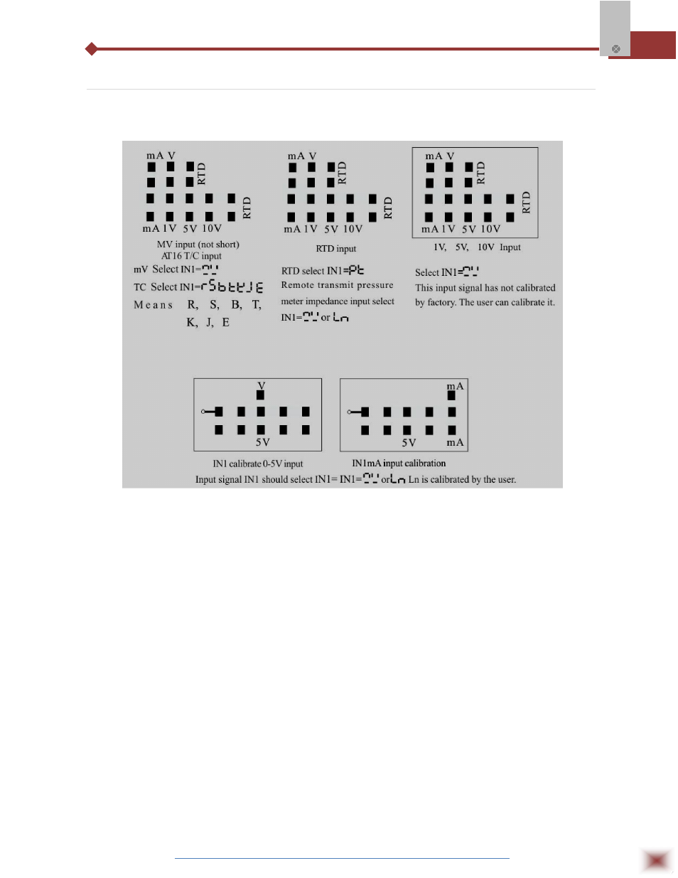
7.4.1 Additional A4000/A4000 16-bit input signal selection
7.4.2 Additional notes of manipulate operator/ electronic-machine driver.
1. When the adjustor is a non-electronic machine control output, all key operations are the
same as stated before.
2. When the adjustor is non-electronic machine (required the electronic machine driver must
have Low-High location equipment.) control output, some parameters should be modified as
follows:
HY:
Blind spot of motor control setting. Range: 1.0-5.0%
Ct:
The running time of full open to full close to full open. Range: 20-250 seconds.
AL1:
Normal alarm mode.
OUTL:
Value output law value. Range: 0.0 ~ 50.0%.
AL2:
Change to motor positive-tune control.
OUTH:
Value output high value. Range: 30.0 ~ 100.0%
OUT:
Motor reverse-turn control.
3. Displaying operations:
PV displays the measuring value.
SV lamp on displaying preset value, SV lamp flashes displaying value feedback value,
MV lamp on displaying control output value.