2 unitilite installation and connection, 1 unitilite rear panel, 2 mains power connection – Naim Audio UnitiLite User Manual
Page 5: 3 fm/dab aerial connection, 4 audio signal connections, Installation and connection
3
Installation and Connection
2.2 Mains Power Connection
Connect UnitiLite to a mains power socket using either the
mains cable supplied or a Naim Power-Line.
2.3 FM/DAB Aerial Connection
If your UnitiLite includes the optional FM/DAB tuner module
it will require a strong, interference-free signal to enable
high quality FM and DAB reproduction. The UnitiLite rear
panel FM/DAB Aerial socket should be connected, via 75
Ohm low-loss coaxial cable, to a suitable aerial. The aerial
should be mounted clear of large obstructions and as high
as possible; ideally on a roof.
Note:
Your local retailer should be able to offer advice on
a suitable aerial and aerial installer.
2.4 Audio Signal Connections
2.4.1 Audio Signal Inputs
UnitiLite provides three stereo analogue inputs and five
S/PDIF digital inputs including one combined analogue/
digital input socket. Connection to the inputs is made via
a variety of socket types. The following table lists the inputs
and their socket types:
Input Type
Socket
an. 1
Analogue
RCA phonos
an. 2
Analogue
RCA phonos
front panel
Analogue
3.5mm jack
Digital
3.5mm mini-TosLink jack
dig. 1
Digital
Coaxial (RCA phono)
dig. 2
Digital
Optical (TosLink)
dig. 3
Digital
Coaxial (RCA phono)
dig. 4
Digital
Optical (TosLink)
Note:
The front panel analogue/digital jack socket can
accept both conventional analogue 3.5mm plugs and
mini-TosLink optical digital plugs. It will automatically
identify the type of plug inserted and handle the signal
appropriately.
Always use high quality interconnect cables to connect
sources to UnitiLite inputs.
2 UnitiLite Installation and Connection
UnitiLite should be installed on an equipment stand intended for the purpose. Do not
stand it directly on top of another item of equipment and ensure it is well ventilated. Care
should be taken to ensure that it is level. It should be installed in its final location before
connecting cables or switching on. UnitiLite has no standby mode and is intended to be
left switched on.
Connecting UnitiLite to mains power and to a variety of audio peripherals and sources
is described in the following paragraphs. Diagram 2.1 illustrates the UnitiLite rear panel
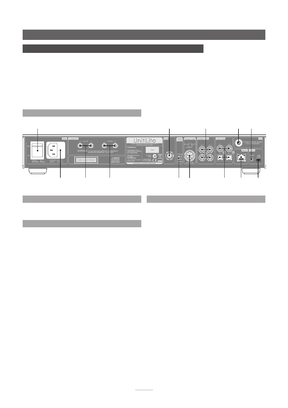
connection sockets.
2.1 UnitiLite Rear Panel
mains input
and fuse
power
switch
wireless (Wi-Fi)
antenna socket
FM/DAB aerial
socket (optional)
analogue
inputs
remote
control
input
signal ground
switch
network
socket
USB
update
socket
left
speaker
right
speaker
digital
inputs
preamp
output