Theory of operation – Nexen Air Volume Booster 964228 User Manual
Page 2
2
FORM NO. L-20314-A-1099
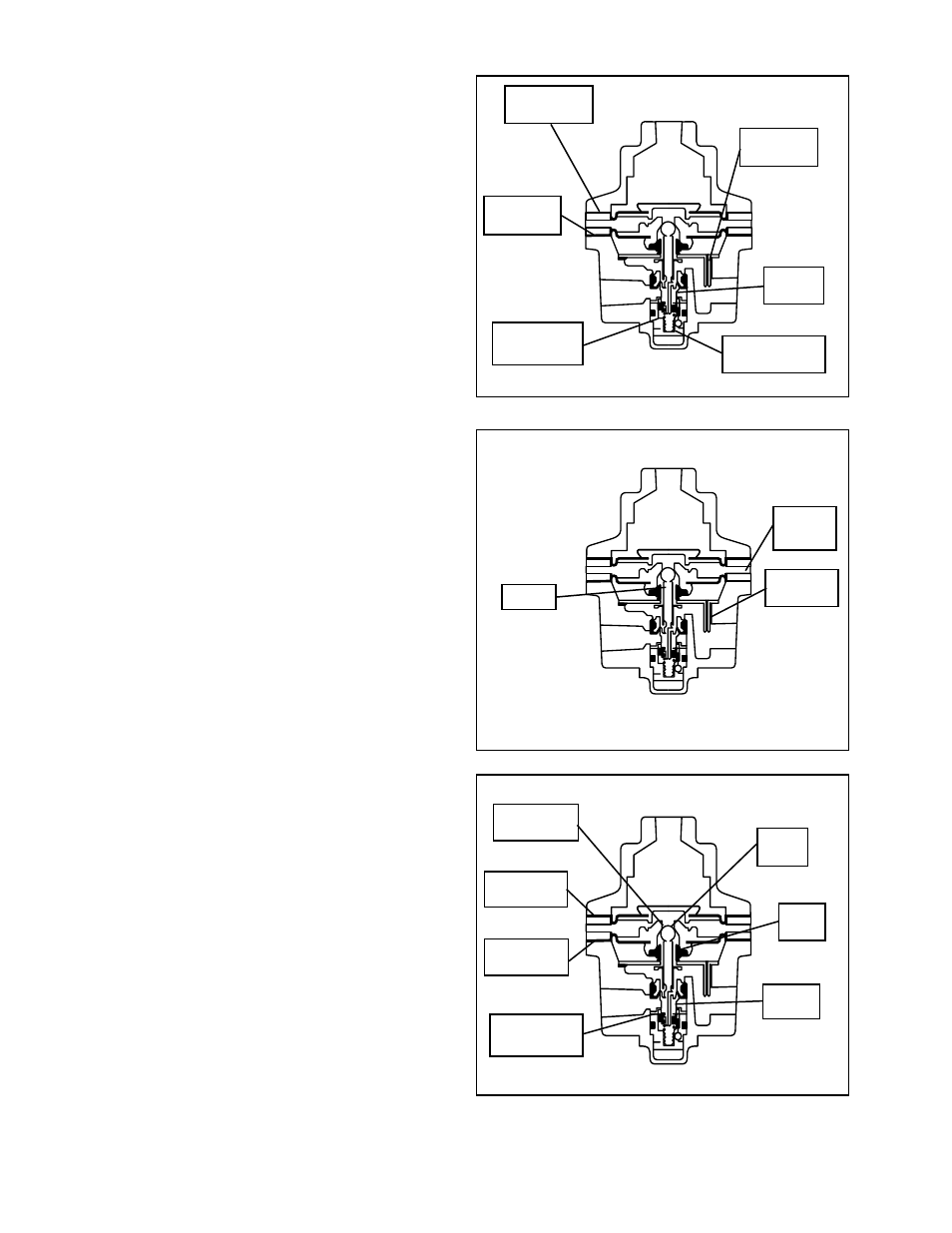
THEORY OF OPERATION
The Nexen Air Volume Booster is a high capacity volume
amplifier that speeds up response in pneumatic lines, valve
motors, and air cylinders.
When supply pressure is introduced to the inlet port of the
Nexen Air Volume Booster, it acts on the balance diaphragm
and on the supply valve so that upward and downward forces
are balanced. The supply valve spring keeps the valve
against the seat preventing flow of supply air to the outlet
port (See Figure 1).
When pressure is applied to the signal port of the Nexen Air
Volume Booster, pressure is exerted against the signal
diaphragm area and as a result, a downward force is exerted
against the top of the diaphragm. Downstream pressure is
communicated through the aspirator tube and exerts
pressure against the bottom of the control diaphragm (See
Figure 1).
This force, added to the force exerted by the supply valve spring
in the upward direction and transmitted through the pintle,
results in a pressure P
O
equals P
S
where P
O
is output pressure,
P
S
equals signal pressure. This condition is not achieved until
output pressure reaches the desired set point (See Figure 2).
When the output reaches the desired set point, the force
due to the action of signal pressure on the signal diaphragm
will move the diaphragm assembly down and through the
pintle, causing the supply valve to open and allow air to be
routed to the outlet port. Outlet (downstream) pressure is
transmitted through the aspirator tube to the control chamber
and sensed by the control diaphragm, aided by the supply
valve spring force, causing the diaphragm assembly to move
upward against the force of the signal pressure acting on
the top of the signal diaphragm. This force, acting through
the pintle, allows the supply valve to throttle, maintaining
the output pressure. Downstream pressure acts on the top
of the supply valve and on the bottom of the balance
diaphragm. Air at atmospheric pressure is communicated
through the vent in the ring spacer and is present on the top
of the relief valve (See Figure 2).
When set point is reached, the force acting on the bottom of
the control diaphragm is in balance with the force acting on
the top of the signal diaphragm. At this point, the force due
to the supply pressure acting on the supply valve and the
force due to supply pressure acting on the top of the balance
diaphragm is in balance. The force due to downstream
pressure acting on the top of the supply valve and the force
due to downstream pressure acting on the underside of the
balance diaphragm are in balance. As downstream pressure
increases above set point, the force on the bottom of the
control diaphragm moves the diaphragm assembly up,
allowing the supply valve to be seated. As the diaphragm
assembly continues to move up, sliding on the seal tube,
the relief valve seat moves away from the relief valve.
Exhaust air vents through holes in the ring spacer (See
Figure 3).
If the down stream pressure decreases below set point, the
pressure decrease is communicated through the aspirator
tube to the bottom of the control diaphragm. A decrease in
pressure on the control diaphragm will cause the diaphragm
assembly to move down, lowering the relief seat against the
relief valve. As the downward movement of the diaphragm
assembly continues, the supply valve will open and increase
downstream pressure until set point valve is reached (See
Figure 3).
FIGURE 1
FIGURE 2
FIGURE 3
Signal
Diaphragm
Control
Diaphragm
Aspirator
Tube
Supply
Valve
Supply Valve
Spring
Balance
Diaphragm
Signal
Pressure
P
S
Pintle
Inlet
Outlet
P
O
Ring
Spacer
Aspirator
Tube
Relief Valve
Seat
Relief
Valve
Seal
Tube
Supply
Valve
Signal
Diaphragm
Control
Diaphragm
Balance
Diaphragm