Nexen RSTC1100 964528 User Manual
Page 9
9
FORM NO. L-21204-C-0705
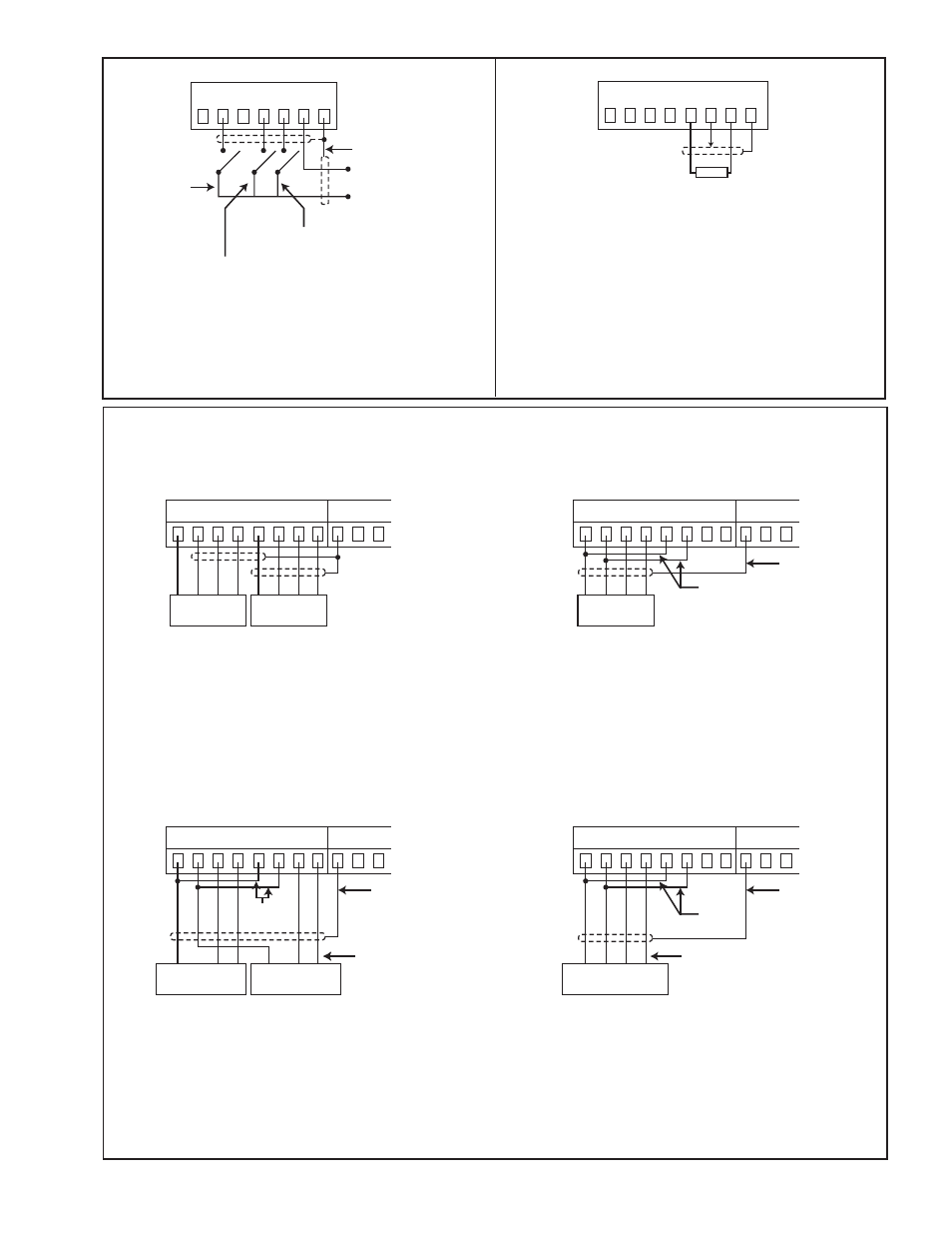
CFL or Single Full Bridge Strain Gauge Load Cell
24 25 26 27 28 29 30 31 32 33 34
No. 2
Sensor
No. 1
Sensor
B
R
W
G
B
R
W
G
Dual MB
Single MB
24 25 26 27 28 29 30 31 32 33 34
Sensor
B
R
W
G
Cable
Shield
Add
Sensor 2
R
B
W
SW Sensor Colors
–Vex
+Vex
Vsig
24 25 26 27 28 29 30 31 32 33 34
Sensor 1
B
R
W
Cable
Shield
Add
Jumpers
SW Sensor Colors
–Vex
+Vex
Vsig
SW or Half Bridge Strain Guage Load Cell
24 25 26 27 28 29 30 31 32 33 34
Sensor
B
R
W
G
Cable
Shield
Add
CFL Sensor Colors
–Vex
+Vex
–Vsig
+Vsig
Figure 6
Control Input Signals
NOTE: To isolate the Control Input Signals, use a power
supply that is separate from the RSTC power supply.
Figure 8
Load Cell Connections
40 41 42 43 44 45 46
Cable Shields
+12 to + 24 VDC
DC Common
Run/Stop
Splice A
Splice B
32 33 34 35 36 37 38 39
1–5 kΩ
Potentiometer
NOTE: Potentiometer can be replaced with analog
voltage signal by connecting analog signal (0-12V
maximum) to terminal 37 and signal common to
terminal 38.
Figure 7
Remote Tension Setpoint