Sensor installation, Projector – Nexen AS 10 912721 User Manual
Page 8
2
FORM NO. L-20355-B-0200
B
A
A
C
L
Machine
11.02
(280MM)
Sensing Length
11.02
(280MM)
Sensing Length
LEFT SENSOR
RIGHTSENSOR
WEB
FIGURE 2 Sensor Viewing Area
SENSOR INSTALLATION
FIGURE 1 Mounting the AWL 280 Sensors
Cable 100mm
(with connectors)
Effective sensing length
11.02 [280]
0.78
[20]
1.77
[45]
0.59 [15]
0.59
[15]
1.18
[30]
4 - 09
3.74
[95]
7.87
[200]
2.36
[60]
14.96
[380]
1.18
[30]
1.18
[30]
3.35
[85]
1.97
[50]
2.56
[65]
Projector
Projector
Detector
Detector
Invert order and align on gap
Vertical Web Pass Line
.985
[25mm]
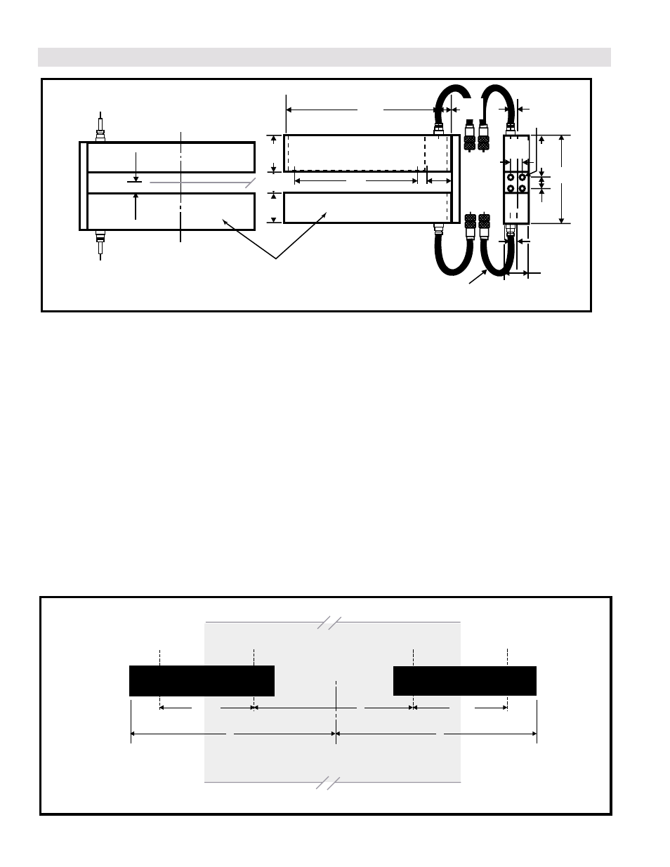
NOTE: Refer to Figures 1 and 2.
1.
Install the two AWL280 Sensors in inverted order to each other; one sensor with the projector side up and one sensor with
the detector side up. Because the detector housing is larger (3.35 inches / 85 mm) than the projector housing (2.56
inches/ 65 mm), the sensor with the detector side up will sit higher than the sensor with the projector side up.
2.
The web must be centered on both the vertical and horizontal plane. Center the web on the vertical plane at the vertical
web pass line between the projector and detector (.985 inch [25 mm]). Center the web on the horizontal plane between
the left and right sensor.
3.
The projector and detector housings may be removed from the steel bar and mounted separately if your application
requires a gap that is wider than 1.978 [50] or if the sides must be open. The housings must be aligned both vertically and
horizontally when mounted separately. The gap from the projector lens to the detector lens must not exceed 10 inches
[250 mm].
4.
The sensing length in the sensor window measures 11.02 inches [280 mm]. This sensing length is indicated by arrows
that are located on either side of the sensor window. However, for the most effective use of this sensing area, the web
should not extend to the full outer edge of the sensing length. The optimum width of the web is 1/2 of the total sensing
area of 22.04 inches plus "B" ( which is 11.02 inches [280 mm] plus "B"). The web width should not exceed 22.04 inches
plus "B" nor should the web width fall below the width of "B". Mount the sensors so that the maximum and minimum web
widths fall within this range. In addition, mount each sensor an equal distance (A) from the center line of the machine.