Nexen AS 10 912721 User Manual
Page 15
9
FORM NO. L-20355-B-0200
CALIBRATION (continued)
RIGHT HAND SENSOR CALIBRATION.
Use an opaque sheet of material to completely block
light projection from the projector to the detector of the
right sensor (see Fig 8).
Connect the negative lead of a DMM to the "COM" test
pin on the main printed circuit board. Connect the
positive lead to the "OUT-R" test pin on the main
printed circuit board (See Fig. 9).
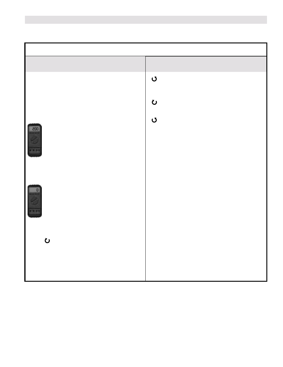
Adjust the "BIAS-R" trim pot until the DMM
indicates +200 ± 5mV (See Fig. 11).
Remove opaque material.
Adjust the "GAIN-R" trim pot until the DMM
indicates 0 ± 5mV (See Fig. 11).
If you can not achieve 0 ± 5mV DC, then increase the
intensity of the projector LEDs by adjusting the LED-R
trim pot
clockwise until 0 ± 5mV is achieved and
then recheck the sensor calibration.
NOTE: If your web application has required that you
increase the gap beyond the standard 1.95 [50 mm],
then you may need to increase the intensity of the
projector LEDs in order to achieve 0 ± 5mV DC.
Right HAND SENSOR ALARM CIRCUIT
ADJUSTMENT.
Turn the "ALARM-R" trim pot fully counter
clockwise. The right LED on AS10-D front panel
that is labeled "Detector Dark" will turn "Off"
Turn the "ALARM-R" trim pot clockwise until the
LED comes "ON".
Turn the "ALARM-R" trim pot counter clockwise
slowly and stop when the LED goes out.
To test the circuit, insert four or five sheets of clear film
about 2 inches [50 mm] wide into the alarm sensor's
light path (See Fig. 10). The right LED on AS10-D
front panel that is labeled "Detector Dark" will turn
"ON".
Right Hand Calibration
Refer to figures 8, 9, 10 and 11.