Replacement procedure–friction facings – Nexen 1625 Input Unit 936001 User Manual
Page 9
9
21070-D-0707
REPLACEMENT PROCEDURE–FRICTION FACINGS
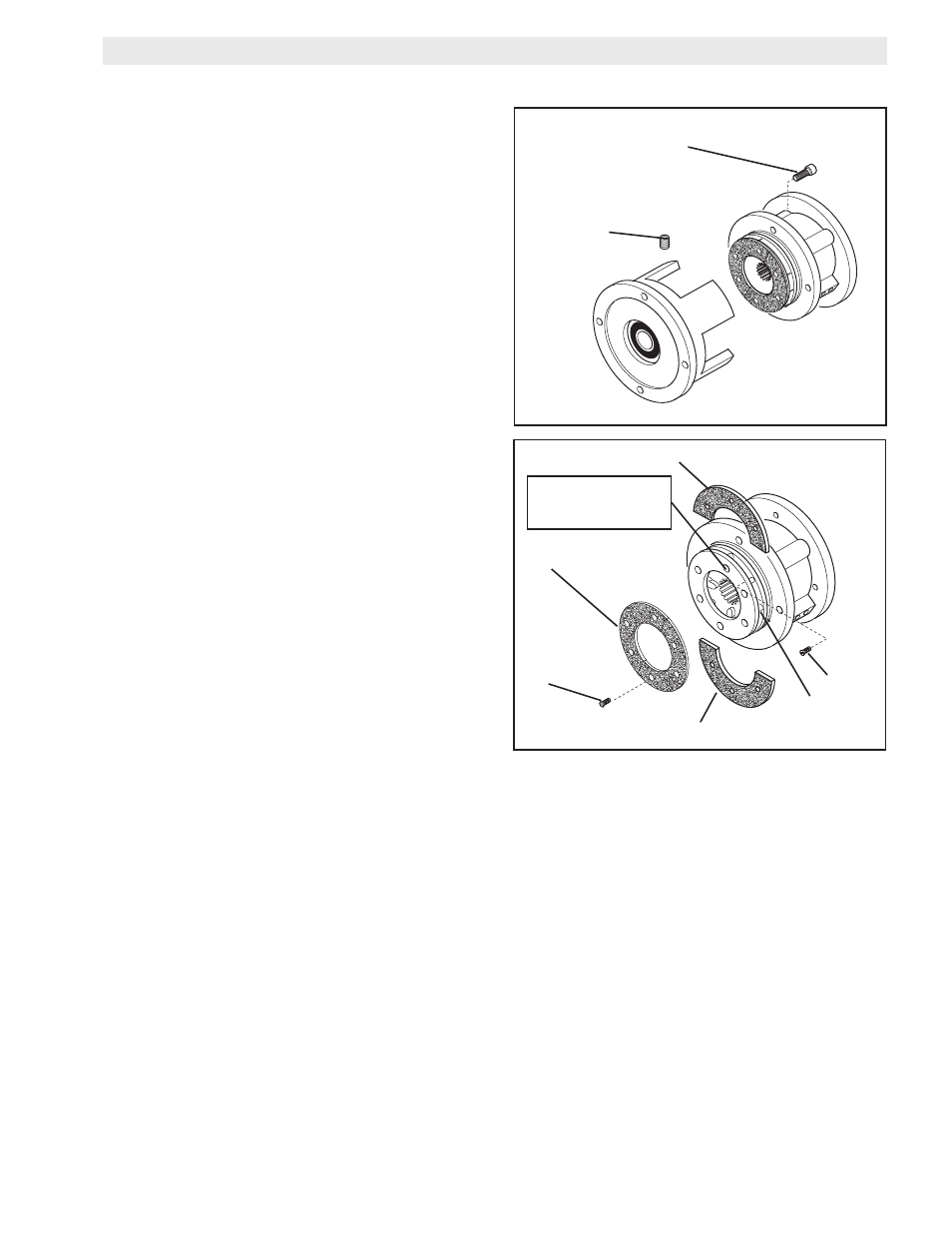
1. Remove the four Socket Head Cap Screws (Item 15)
and separate the two halves of the FMCB (See Figure
8).
2. Remove the six old Flat Head Screws (Item 12) and the
first old Friction Facing (Item 11) (See Figure 9).
3. Align the holes in the Splined Disc (Item 9) with the Flat
Head Screws (Item 12) that secure the second split
Friction Facing (Item 13) (See Figure 9).
4. Remove the six old Flat Head Screws (Item 12) and the
second old Friction Facing (Item 13) (See Figure 9).
5. Install the first new split Friction Facing (Item 13) and
new Flat Head Screws (Item 12).
6. Tighten the six new Flat Head Screws (Item 12) to 71
in-lbs (8.02 N-m) torque.
7. Install the second new Friction Facing (Item 11) and
new Flat Head Screws (Item 12) (See Figure 9).
8. Tighten the six new Flat Head Screws (Item 12) to 71
in-lbs (8.02
N-m) torque.
9. Apply a drop of Loctite® 242 to the threads of the
Socket Head Cap Screws (Item 15) (See Figure 8).
10. Install and tighten the four Socket Head Cap Screws
securing the two halves of the FMCB to 509 in-lbs (57.5
FIGURE
FIGURE 9
12
11
13
12
Insert screwdriver
to remove second
split Friction Facing.
13
SET SCREW
(Item 3)
SOCkET HEAD CAP SCREW
(Item1)
9