Installation – Nexen 1625 Input Unit 936001 User Manual
Page 4
21070-D-0707
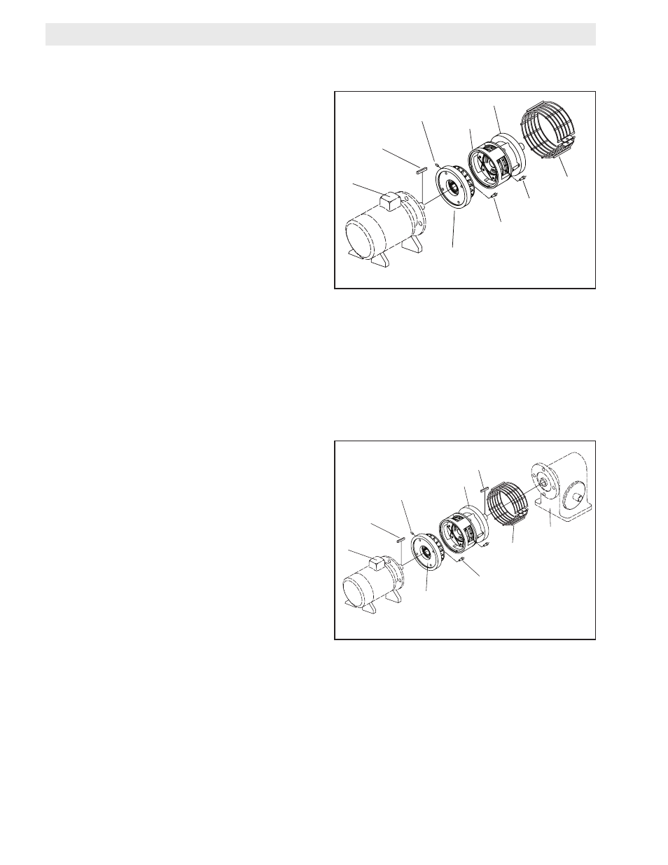
NOTE: Refer to Figure 1.
1. Insert the customer supplied key into the motor shaft
keyway.
2. Remove the four Socket Head Cap Screws, (Item 8), to
separate the Female Pilot, (Item 1), from the Housing
(Item 7).
3. Secure the Female Pilot (Item 7) to the motor face us-
ing Nexen supplied socket head cap screws. Tighten
customer supplied cap screws to 1425 in-lbs (161 N-m).
4. Tighten the Set Screw (Item 35) to 275 in-lbs (31 N-m).
5. Secure Housing (Item 7) to the Female Pilot (Item 1)
using Socket Head Cap Screws (Item 8). Apply Loctite
®
242 to the threads of Item 8.
6. Tighten Socket Head Cap Screws to 509-662 in-lbs
(57.5-74.8 N-m).
7. Install the Housing Guard (Item 34) over the open
areas of the FMCB, and secure it using the provided
fasteners.
FIGURE 1
FIGURE 2
NOTE: Refer to Figure 2.
1. Insert the Key (Item 33) into the output shaft of the
FMCB-1625.
2. Slide the FMCB output shaft into the gear reducer.
3. Secure the FMCB to the gear reducer using customer
supplied cap screws and lock washers.
4. Complete steps 1-7 from Section A.
INSTALLATION
SECTION A: MOUNTING ON THE SHAFT END OF A MOTOR
SECTION B: MOUNTING BETWEEN A GEAR REDUCER AND MOTOR
MOTOR
CUSTOMER
SUPPLIED kEy
SET SCREWS
(Item 3)
HOUSING
(Item )
FMCB
.00-13 SOCkET
HEAD CAP SCREWS
CAP SCREWS
(Item )
HOUSING
GUARD
FEMALE PILOT
(Item 1)
MOTOR
CUSTOMER
SUPPLIED kEy
SET SCREWS
(Item 3)
FMCB
.00-13 SOCkET
HEAD CAP SCREWS
HOUSING
GUARD
FEMALE PILOT
(Item 1)
GEAR
REDUCER
key
(Item 33)