Nexen FMCB-7-38 801613 User Manual
Page 16
16
FORM NO. L-20179-H-1209
18. Slide the Piston (Item 17) into the Air Chamber (Item
14).
19. Support the inner race of the Bearing (Item 2 or 18)
and press the Splined Disc (Item 9) into the Bearing
and Piston (Item 17).
20. Reinstall the Retaining Ring (Item 6 or 20) that secures
the Splined Disc to the Bearing (Item 2 or 18).
21. Apply a drop of Loctite
®
242 to the threads of the
Socket Head Cap Screws (Item 8 or 15).
22. Reinstall and tighten the four Socket Head Cap
Screws (Item 8 or 15) securing the Air Chamber
(Item 14) to the Housing (Item 7) to the recommended
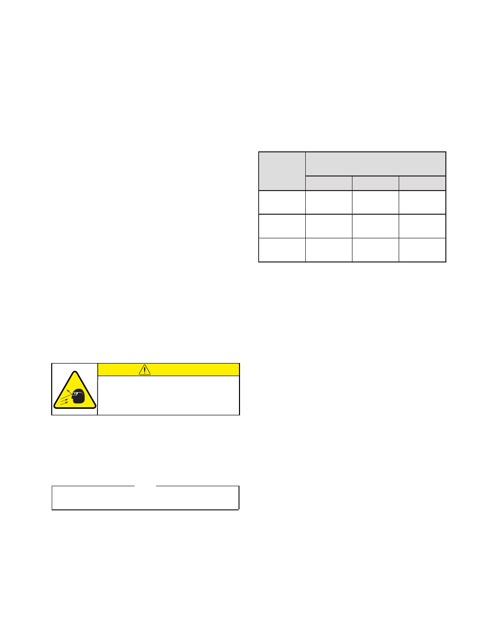
torque (See Table 2) .
23. Remove the old O-Ring Seals (Items 23 and 24) from
the cylinder (Item 22).
24. Coat the O-Ring contact surfaces of the Cylinder
(Item 22) and the new O-Ring Seals (Items 23 and
24) with a thin film of O-Ring lubricant and install the
new O-Ring Seals.
25. Align the Spring Pin (Item 25) in the Cylinder (Item
22) with the hole in the Piston (Item 17); then, slide
the Cylinder into the Piston.
26. Apply a drop of Loctite
®
242 to the threads of the
Socket Head Cap Screws (Item 8 or 26).
27. Reinstall and tighten the four Socket Head Cap
Screws securing the Cylinder (Item 22) to the Air
Chamber (Item 14) to the recommended torque (See
Table 2).
B
C
M
F
l
e
d
o
M
w
e
r
c
S
p
a
C
d
a
e
H
t
e
k
c
o
S
e
u
q
r
o
T
g
n
i
n
e
t
h
g
i
T
d
e
d
n
e
m
m
o
c
e
R
8
m
e
tI
5
1
m
e
tI
6
2
m
e
tI
8
2
-
7
m
N
6
.
9
1
]
b
l-
tf
5
.
4
1
[
--
-
m
N
7
.
6
1
]
b
l-
tf
3
.
2
1
[
8
3
-
8
m
N
2
.
3
3
]
b
l-
tf
5
.
4
2
[
m
N
1
.
7
6
]
b
l-
tf
5
.
9
4
[
--
-
2
4
-
8
--
-
m
N
1
.
7
6
]
b
l-
tf
5
.
9
4
[
m
N
2
.
3
3
]
b
l-
tf
5
.
4
2
[
Table 2
Male PIlOT BearInG
FMCB 7-28, 8-38, anD 8-42
refer to Figure 15.
1. Remove the Retaining Ring (Item 32) from the Stub
Shaft (Item 31).
2. Press the Stub Shaft (Item 31) out of the Male Pilot
(Item 27).
note
One Bearing (Item 29) will come out of the Male Pilot
(Item 27) attached to the Stub Shaft (Item 31).
3. Remove the old Bearing (Item 29) from the Stub Shaft
(Item 31).
4. Press the second old Bearing (Item 29) out of the
Male Pilot (Item 27).
5. Clean the bearing bore of the Male Pilot (Item 27)
with fresh safety solvent, making sure all old Loctite
Ò
residue is removed.
6. Press the first new Bearing (Item 29) onto the Stub
Shaft (Item 31).
7. Apply an adequate amount of Loctite
®
680 to evenly
coat the outer race of the new Bearing (Item 29).
8. Carefully align the outer race of the new Bearing (Item
29) with the bore of the Male Pilot (Item 27).
9. Supporting the Male Pilot (Item 27) and pressing on
the outer race of the new Bearing (Item 29), press the
first new Bearing and Stub Shaft into the Male Pilot.
10. Apply an adequate amount of Loctite
®
680 to evenly
coat the outer race of the second new Bearing (Item
29).
CAUTION
Working with spring loaded or tension
loaded fasteners and devices can cause
injury. Wear safety glasses and take the
appropriate safety precautions.
Male PIlOT BearInG anD O-rInG SealS continued
- FMCB-8-42 801619 FMCB-8-38 801616 FMCB-130-19 801400 FMCB-130-24 801403 FMCB-7-28 801610 FM 7-28 Input Unit 801627 FM 7-28 Input Unit 801575 FM 8-38 Input Unit 801629 FM 8-38 Input Unit 801601 FM 7-38 Input Unit 801628 FM 7-38 Input Unit 801608 FM 8-42 Input Unit 801630 FM 8-42 Input Unit 801602 FMCBE-875 801428 FMCBE-7-38 801638 FMCBE-7-28 801637 FMCBE-8-38 801639 FMCBE-8-42 801640