Installation – Nexen MCB-800 830853 User Manual
Page 5
FORM NO. L-21082-E-0110
5
INSTALLATION
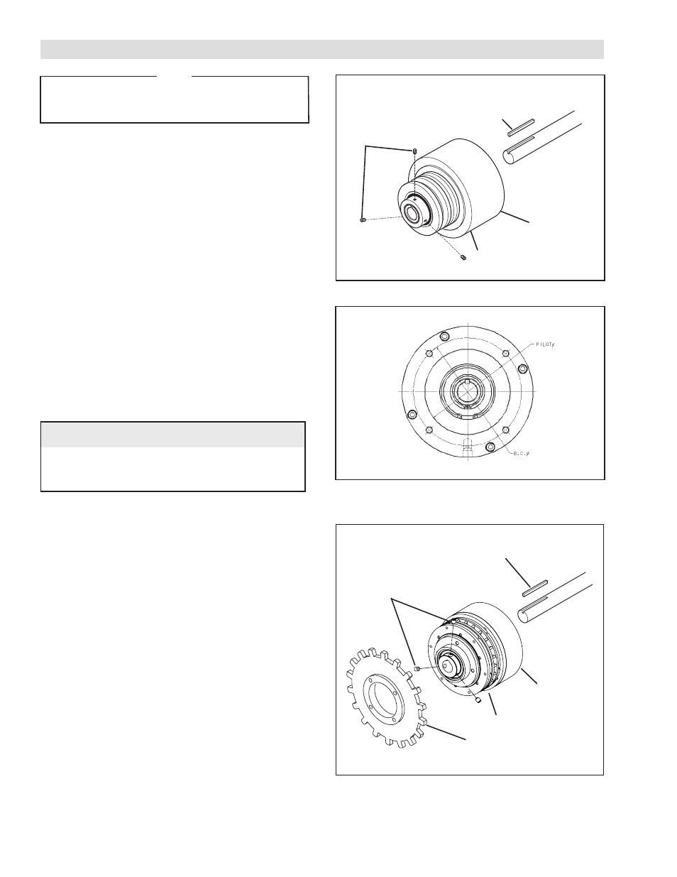
SHEAVE MOUNT CLUTCH/BRAKE
NOTE: Refer to Figure 1.
1. Insert the Key (Item 22) into the machine shaft. Align
the Keyway on the Clutch/Brake with the Key on the
machine shaft. Slide the Clutch/Brake onto the machine
shaft and Key.
2. Install and tighten the Set Screws (Item 20).
3. Align the Clutch/Brake air inlet ports to the six o’clock
down position to allow condensation to drain out of
the ports.
4. Using the tapped holes provided on the back of the
Air Chamber (See Figure 2), secure the air chamber
housing in the direction of rotation only. Do not rigidly
mount the air chamber housing.
PILOT MOUNT CLUTCH/BRAKE
NOTE: Refer to Figure 3.
1. Secure a customer supplied sheave or sprocket to
the Clutch/Brake using the threaded holes in the Pilot
Mount Drive Disc (Item 7).
2. Insert the Key (Item 22) into the machine shaft; then,
slide the Clutch/Brake onto the machine shaft and Key.
3. Install and tighten the Set Screws (Item 20).
4. Align the Clutch/Brake air inlet ports to the six o-clock
down position to allow condensation to drain out of the
ports.
5. Using the tapped holes provided on the back of the
Air Chamber (See Figure 2), secure the air chamber
housing in the direction of rotation only. Do not rigidly
mount the air chamber housing.
FIGURE 1
Set Screws
(Item 20)
Clutch/Brake
Key
(Item 22)
Air Chamber Housing
(Item 3)
FIGURE 3
Set Screws
(Item 20)
Key
(Item 22)
Air Chamber Housing
(Item 3)
Clutch/Brake
Pilot Mount Drive Disk (Item 7)
Unit
0.312-18
0.375-16
0.375-16
TABLE 1
Anti-Rotation
Hole Thread
FCB-450
LCB-600
MCB-800
B.C. Ø
4.750
5.875
7.500
Pilot Ø
3.750
4.500
5.500
FIGURE 2
NOTE
These are "hub-stop" clutch-brakes. They stop the shaft
on which they are mounted. Therefore, they must be
mounted on the driven shaft.