Parts replacement (continued...) – Nexen MCB-800 830853 User Manual
Page 10
10
FORM NO. L-21082-E-0110
PARTS REPLACEMENT (continued...)
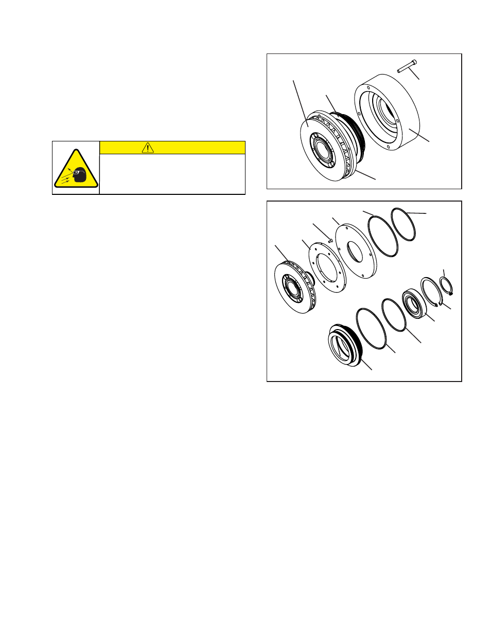
NOTE: Refer to Figure 7.
14. Remove the four Socket Head Cap Screws
(Item 19); then, slide the Friction Disc Hub (Item 5),
Cylinder (Item 4), and Piston (Item 2) out of the Air
Chamber Housing (Item 3).
NOTE: Refer to Figure 8.
15. Remove the Retaining Ring (Item 12) and press the
Friction Disc Hub (Item 5) out of the Cylinder (Item 4)
and Piston (Item 2).
16. Slide the Piston (Item 2) out of the Cylinder (Item 4);
then, remove the old O-ring Seals (Items 17 & 18) from
the Piston and Cylinder.
17. Remove the Retaining Ring (Item 14) from the Piston
(Item 2); then, press the old Ball Bearing (Item 9) out
of the Piston.
18. Clean the bearing bore of the Piston (Item 2) with fresh
safety solvent, making sure all old Loctite
®
(or
equivalent
)
residue is removed.
19. Apply an adequate amount of Loctite
®
680 (or
equivalent
) to evenly coat the outer race of the new Ball
Bearing (Item 9).
20. Supporting the Piston (Item 2) and pressing on the
outer race of the new Ball Bearing (Item 9), press the
new Ball Bearing into the Piston.
21. Reinstall the Retaining Ring (Item 14).
22. Clean the o-ring grooves and o-ring contact surfaces
of the Piston (Item 2), Cylinder (Item 4), and Air
Chamber with fresh safety solvent and lubricate the
o-ring grooves and contact surfaces with fresh o-ring
lubricant.
23. Lubricate the new O-ring Seals (Items 17 & 18) and
install the new O-ring Seals onto the Piston (Item 2)
and Cylinder (Item 4); then, slide the Piston back into
the Cylinder.
24. Remove the six Flat Head Screws (Item 24) and the
old Friction Facing (Item 23) from the Friction Disc Hub
(Item 5).
(continued...)
FIGURE 8
5
23
24
4
18
17
2
18
17
9
14
12
25. Using six new Flat Head Screws (Item 24), secure the
new Friction Facing (Item 23) to the Friction Disc Hub
(Item 5).
26. Alternately and evenly tighten the six flat head screws
(Item 24) to the recommended torque. (See Table 3).
27. Support the inner race of the new Ball Bearing (Item
9) and press the Friction Disc Hub (Item 5) into the
Cylinder (Item 4), Piston (Item 2), and new Ball Bearing
(Item 9).
28. Reinstall the Retaining Ring (Item 12).
FIGURE 7
Friction Disc
Hub (Item 5)
Cylinder (Item 4)
Piston (Item 2)
19
Air Chamber
Housing (Item 3)
CAUTION
Working with spring loaded or tension
loaded fasteners and devices can cause
injury. Wear safety glasses and take the
appropriate safety precautions.