Nexen SE-200 806000 User Manual
Page 5
5
FORM NO. L-20084-G-1209
INSTALLATION
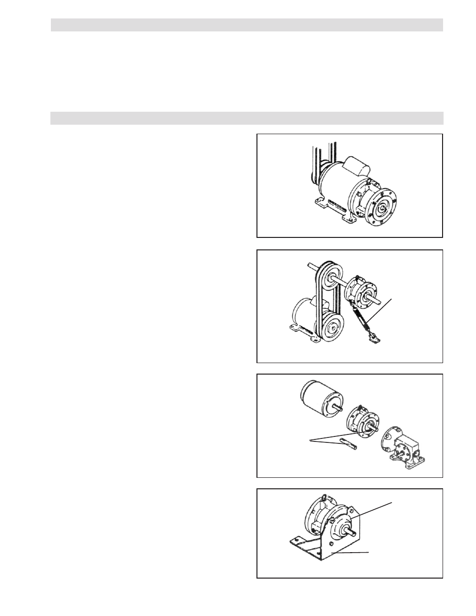
MOTOR SHAFT MOUNTED SE BRAKE
Opposite Drive End on Double “C” Faced Mo tor
Refer to Figure 1.
1. Insert the Key (Item 37) into shaft keyway.
2. Slide the SE Brake onto motor shaft and secure with
mounting bolts.
FIGURE 1
SE BRAKE MOUNTED BETWEEN A MOTOR AND
GEAR REDUCER
Refer to Figure 3.
1. Insert the Key (Item 37) into the shaft keyway.
2. Slide the SE Brake onto motor shaft and secure it
with mounting bolts.
3. Insert the first Key into Adaptor Shaft and insert Adaptor
Shaft into the SE Brake.
4. Insert the second key into Adaptor Shaft; then, insert
Adaptor Shaft into reducer, and bolt the SE Brake and
motor to gear reducer.
Adaptor
Shaft
FIGURE 3
MOUNTING AN OUTPUT UNIT
Refer to Figure 4.
An Output Unit can be mounted to the SE Brake when
a drive through arrangement is desired. The Output Unit
can then be used to mount a sheave, sprocket, or other
desired drive.
With the Output Unit attached, the SE Brake may be
foot mounted to provide a free standing drive through
arrangement (Models SE-100-1 and SE-200-1 only).
Output
Unit
FIGURE 4
Mounting Foot
(Prod. No. 883000)
SHAFT MOUNTED SE BRAKE
with Torque Arm
Refer to Figure 2.
1. Insert the Key (Item 37) into the shaft keyway.
2. Slide the SE Brake onto the shaft.
3. Retain the Key with the set collar.
Torque
Arm
FIGURE 2
INTRODUCTION
Nexen's Air Champ Spring Engaged Brakes offer worker
protection on conveyors, hoists, and other equipment where
fast, dependable stopping may prevent physical injury.
SE Brakes also protect equipment with controlled
engagement where sudden stops may damage valuable
equipment.
When power to the control valve is lost, or air is exhausted,
springs engage the SE Brake, and the load is held in a
stable position. Nexen's SE Brake also incorporates a
manual release, which is used to disengage the brake if
no air pressure is available.