Nexen S-450 827801 User Manual
Page 5
5
FORM NO. L-20087-P-1112
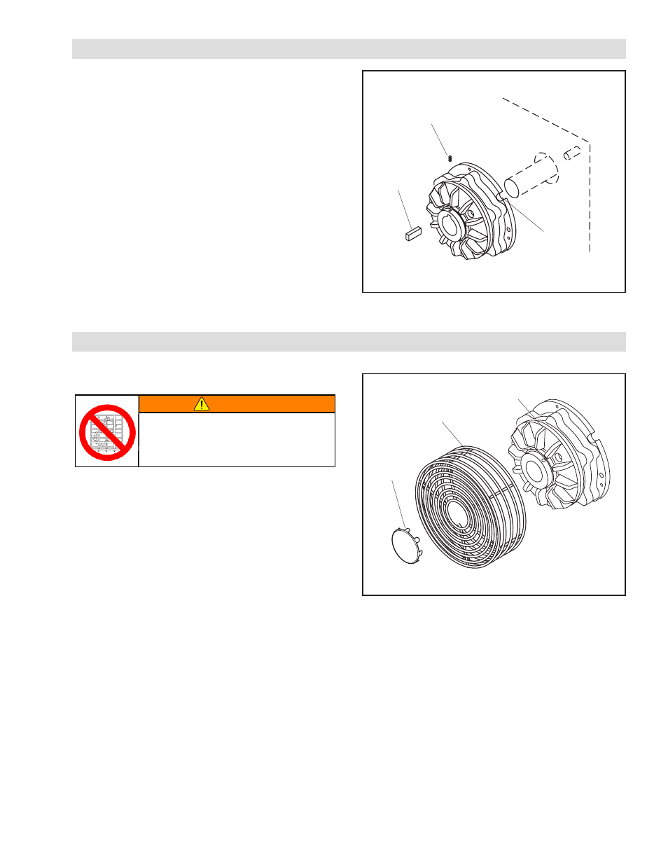
INSTALLATION
1. Insert the Key (Item 16) into the shaft keyway.
2. Slide the brake over the Key and on the shaft.
3. Install and tighten the three Set Screws (Item 17).
4. Align the brake's air inlet to the six o’clock down
position.
5. Using the four holes in the Air Chamber flange or a
torque pin in the slot provided, secure the brake's Air
Chamber (Item 4) to prevent brake rotation.
FIGURE 1
Set Screws
(Item 17)
Key
(Item 16)
Torque
Pin Slot
NOTE: Refer to Figure 1.
BRAKE GUARD INSTALLATION
FIGURE 2
Brake Guard
End Cap
Air Chamber
NOTE: Refer to Figure 2.
1. Align the mounting holes of the Brake Guard with the
four tapped holes in the S-brake Air Chamber.
2. If the Brake Guard is shipped with an End Cap, place
the End Cap over the front of the Brake Guard and
bend the tabs around the Brake Guard to hold the End
Cap in place.
3. Using the four Phillips Head Pan Screws, secure the
Brake Guard to the Brake. Tighten to 35 in-lbs [4
Nm].
4. If additional clearance is required (S-1200/1400),
secure standoffs to air chamber before tightening
fastening screws.
WARNING
Ensure proper guarding of the product is
used. Nexen recommends the machine
builder design guarding in compliance
with OSHA 29 CFR 1910 “Occupational
Safety and Health Hazards”.
- S-450 827800 S-450 827812 S-450 827803 S-450 827804 S-450 827805 S-450 827808 S-450 827806 S-450 827807 S-450 827824 S-450 827814 S-450 827826 S-450 827828 S-450 827811 S-450 827809 S-450 827817 S-450 827823 S-450 827810 S-450 827829 S-450 827822 S-450 827830 S-450 827815 S-450 827816 S-600 827914 S-600 827901 S-600 827903 S-600 827900 S-600 827925 S-600 827928 S-600 827906 S-600 827902 S-600 827919 S-600 827911 S-600 827913 S-600 827915 S-600 827910 S-600 827916 S-600 827917 S-600 827912 S-600 827918 S-800 828000 S-800 828014 S-800 828003 S-800 828020 S-800 828004 S-800 828002 S-800 828001 S-800 828019 S-800 828012 S-800 828022 S-800 828021 S-800 828005 S-800 828009 S-800 828015 S-800 828016 S-800 828018 S-800 828010 S-800 828017 S-800 828031 S-1000 828101 S-1000 828100 S-1000 828112 S-1000 828113 S-1000 828104 S-1000 828103 S-1000 828116 S-1000 828118 S-1000 828107 S-1000 828190 S-1000 828114 S-1000 828119 S-1000 828111 S-1000 828191 S-1000 828115 S-1000 828117 S-1000 828192 S-1000 828110 S-450A 827821 S-450A 827820 S-450A 827827 S-450A 827819 S-450A 827818 S-600A 827908 S-600A 827907 S-800A 828029 S-800A 828008 S-800A 828023 S-600A 827926 S-600A 827905 S-600A 827904 S-600A 827927 S-600A 827921 S-600A 827922 S-600A 827923 S-600A 827924 S-600A 827909 S-800A 828006 S-800A 828007 S-800A 828026 S-800A 828025 S-800A 828032 S-1000A 828122 S-1000A 828121 S-1000A 828126 S-1000A 828108 S-1000A 828109