Nexen DPC-11T 961200 User Manual
Page 7
4
FORM NO. L-20070-F-1209
INSTALLATION (continued)
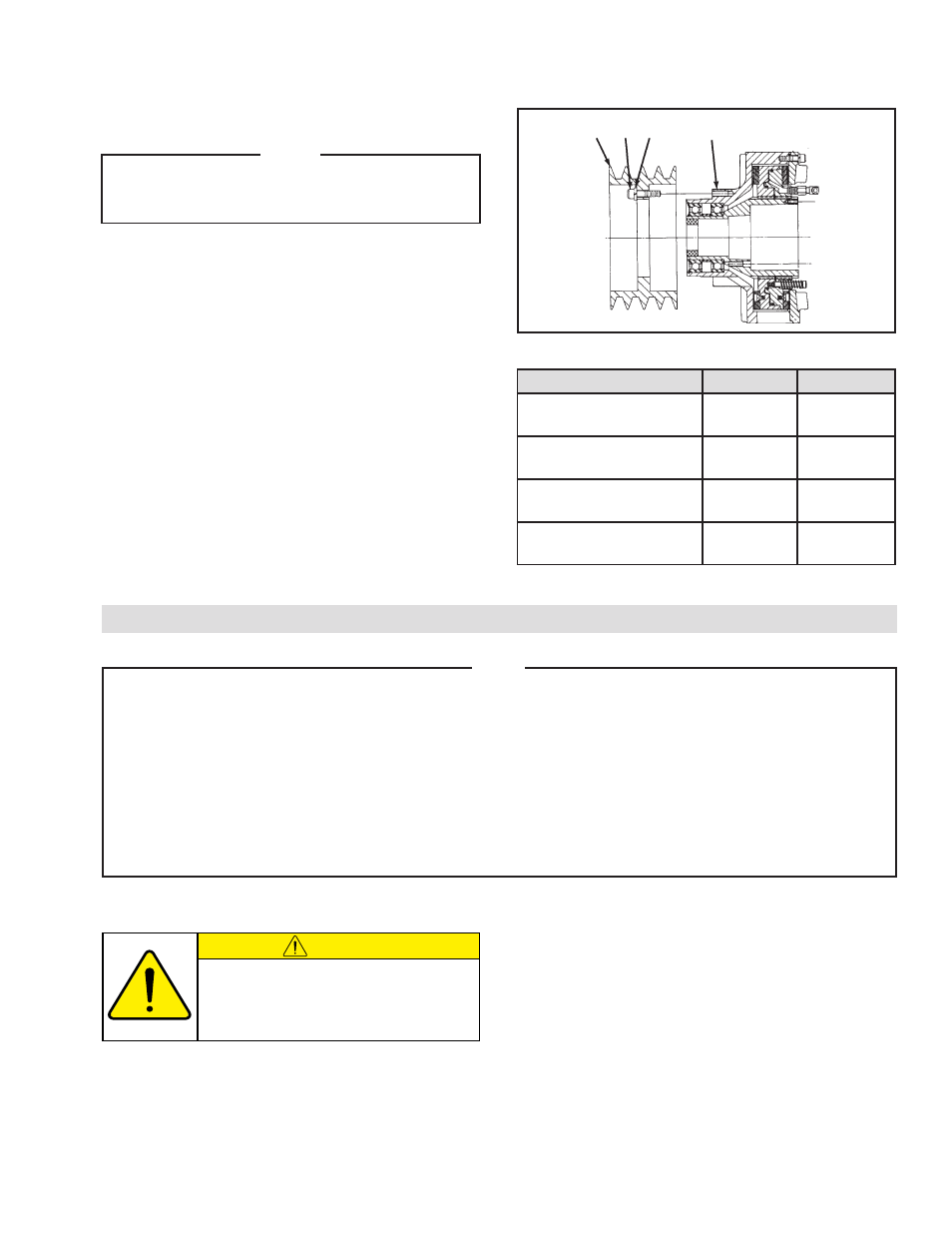
SHEAVE MOUNT
NOTE
The Sheave Clutch is a combination of the Pilot
Clutch and Sheave Assembly (both shipped in
a separate container).
REFER TO FIGURE 3.
1. Slide the Sheave (Item 26) onto the pilot diameter of
the Pilot Clutch Assembly.
2. Align the mounting holes in the Sheave (Item 26)
with the tapped holes in the Housing (Item 5).
3. Install the Cap Screws (Item 28), and Lockwashers
(Item 27).
4. Tighten the Cap Screws (Item 28) to the
recommended torque (See Table 2).
5. Proceed with Steps 1 through 8 from Pilot Mount
Clutch Installation section on the previous page.
28
5
27
26
FIGURE 3
TABLE 2 Recommended Tightening Torques
Description
DPC-9T
DPC-11T
Shoulder Screw (Item 12)
9 ft-lbs
[12 Nm]
9 ft-lbs
[12 Nm]
Cap Screw (Item 15)
48 ft-lbs
[65 Nm]
48 ft-lbs
[65 Nm]
Cap Screw (Item 24)
13 ft-lbs
[18 Nm]
13 ft-lbs
[18 Nm]
Cap Screw (Item 28)
48 ft-lbs
[65 Nm]
48 ft-lbs
[65 Nm]
LUBRICATION
CAUTION
LUBRICATOR DRIP RATE SETTINGS
NOTE
Nexen pneumatically actuated devices require clean, pressure regulated air for maximum performance and
life. All seals in Nexen pneumatically operated devices are lubricated for life, and do not require additional
lubrication.
However, some customers prefer to use an air line lubricator, which injects oil into the pressurized air,
forcing an oil mist into the air chamber. This is acceptable, but care must be taken to ensure once an air
mist lubrication system is used, it is continually used over the life of the product as the oil mist may wash
free the factory installed lubrication.
Locate the lubricator above and within ten feet of the product, and use low viscosity oil such as SAE-10.
Synthetic lubricants are not recommended.
Nexen product's bearings are shielded and pre-lubricated, and require no further lubrication.
These settings are for Nexen supplied
lubricators. If you are not using a Nexen
lubricator, calibration must follow the
manufacturer's suggested procedure.
1. Close and disconnect the air line from the unit.
2. Turn the Lubricator Adjustment Knob
counterclockwise three complete turns.
3. Open the air line.
4. Close the air line to the unit when a drop of oil forms
in the Lubricator Sight Gage.
5. Connect the air line to the unit.
6. Turn the Lubricator Adjustment Knob clockwise until
closed.
7. Turn the Lubricator Adjustment Knob
counterclockwise one-third turn.
8. Open the air line to the unit.