Nexen DPC-11T 961200 User Manual
Page 11
8
FORM NO. L-20070-F-1209
CAUTION
PARTS REPLACEMENT
FRICTION FACING (ITEM 4)
NOTE
Inspect Friction Facings for wear, and replace
when they are appropriately 9/32" thick. Friction
Facings can be replaced without removing the
DPC Clutch from the motor shaft.
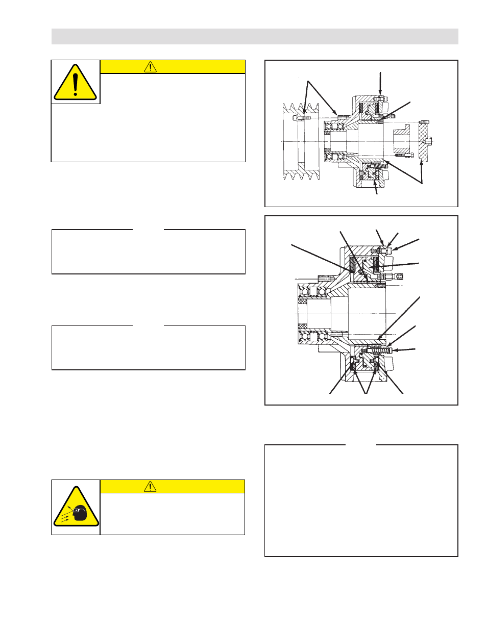
REFER TO FIGURE 7.
1. Disconnect the air supply and Hose Assemblies at
the Piston/Drive Disc Elbow Fittings.
NOTE
If the “DPC” Clutch is shaft end mounted; remove
the Rotary Air Union Cap (Item 25). On through
shaft installation; remove the Elbow Fittings
(Item 20) from the shaft.
2. Remove Cap Screws (Item 15) and Lockwashers
(Item 14).
3. Remove the Friction Disc (Item 6).
4. Remove Shoulder Screws (Item 12) and Springs
(Item 13).
5. Slide the Piston/Drive Disc (Item 2) off of the Splined
Hub (Item 1).
FIGURE 6
Alignment
Mark
Alignment Mark
Alignment
Mark
Alignment
Mark
Alignment Mark
The Nexen DPC Clutch has been balanced
at the factory. During disassembly, mark
components with chalk alignment marks to
insure correct alignment and balance as the DPC Clutch
is reassembled (See Figure 6).
When reassembling the Nexen DPC Clutch, make sure all
screws are tightened to the recommended torque (See
Table 4 in OPERATIONS SECTION).
CAUTION
Working with spring loaded or tension
loaded fasteners and devices can cause
injury. Wear safety glasses and take the
appropriate safety precautions.
8. Remove the Machine Screws (Item 11), and replace
worn Friction Facings (Item 4).
NOTE
On some models of the DPC-9T and DPC-11T,
the Machine Screws (Item 11) are assembled
with a green anaerobic thread locking
compound. If remove is difficult, strike the end
of the screwdriver with a hammer to break the
crystalline structure of this locking compound
before attempting to remove the screws. The
Machine Screws (Item 11) that are furnished
with new Friction Facings have a locking patch,
and do not require the use of a thread locking
compound.
9. Reverse Steps 1 through 7 to reassemble the DPC
Clutch, noting chalk alignment marks and tighten all
screws to the recommended torque (See Table 4).
6. Remove the Retaining Ring (Item 10).
7. Slide the Cylinder/Drive Disc (Item 3) off of the
Splined Hub (Item 1).
11
4
3
10
6
14
15
2
1
13
12
11
FIGURE 7