Field connected water piping, General, Load and source piping connections – WaterFurnace Envision Hydronic (NDW) User Manual
Page 8
8
NDW INSTALLATION MANUAL
General
Each unit is equipped with captive 2 in. [50.8 mm] FPT water
connections to eliminate ‘egg-shaping’ from use of a backup
wrench. For making the water connections to the unit, a Teflon
tape thread sealant is recommended to minimize internal
fouling of the piping. Do not over tighten connections.
NOTE: Units are factory run-tested using propylene
glycol. Prior to connecting piping to unit, thoroughly
flush heat exchangers.
The piping installation should provide service personnel
with the ability to measure water temperatures and
pressures. The water lines should be routed so as not to
interfere with access to the unit. The use of a short length
of high pressure hose with a swivel type fitting may simplify
the connections and prevent vibration. Optional stainless
steel hose kits are available as an accessory item.
Before final connection to the unit, the supply and return
hose kits must be connected, and the system flushed
to remove dirt, piping chips and other foreign material.
Normally, a combination balancing and close-off (ball) valve
is installed at the return, and a rated gate or ball valve is
installed at the supply. The return valve can be adjusted to
obtain the proper water flow. The valves allow the unit to
be removed for servicing. Both source as well as load fluid
piping must be at least as large as the unit connections on
the heat pump (larger on long runs).
Never use flexible hoses of a smaller inside diameter than
that of the water connection on the unit and limit hose length
to 10 ft. per connection. Check carefully for water leaks.
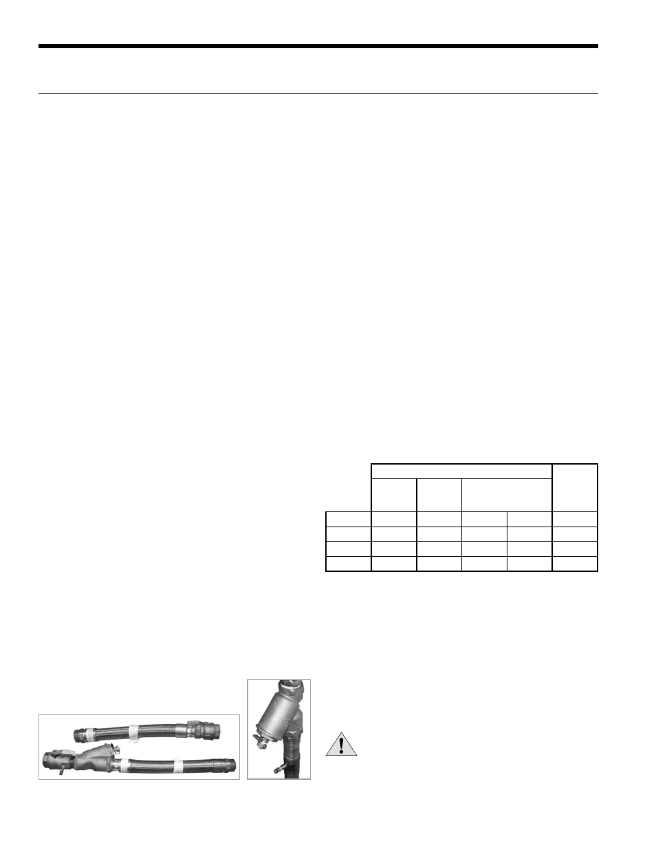
Load and Source Piping Connections
The NDW Series has two connection options available. Each kit
is intended to connect one piping connection. Therefore, two
kits will be required for each unit. The kits can be mixed for
installer convenience, one on source and the other on load.
CKNDW1 - Strainer Connection Kit includes a 2” copper tee with
integral P/T plug and a 2” “Y” strainer. Other components to
complete the all copper piping can be sourced locally.
HHK162S - Strainer Hose Kit set includes 2” Hose kit includes
a 2” stainless steel braided hose with integral P/T plug and 2”
“Y” strainer.
Field Connected Water Piping
Water Flow Rate
The proper water flow must be delivered to each unit
whenever the unit heats or cools. To assure proper flow,
the use of pressure/temperature ports is recommended
to determine the flow rate. These ports should be located
adjacent to the supply and return connections on the unit.
The proper flow rate cannot be accurately set without
measuring the water pressure drop through the refrigerant-
to-water heat exchanger (See Pressure Drop Table for water
flow and pressure drop information).
Load Flow Rate
The load flow on all water to water products including the
NDW Series should be 3 gpm per ton (typically the rated
flow and the highest flow shown in the capacity charts).
Refer to the table below. This flow rate is required especially
when heating water to limit the effects of the higher
condensing temperatures of water heating for radiant floor
heating or domestic water use.
Source Flow Rate
The source flow can range between 2.25 and 3 gpm per
ton for earth loops. For open loop well water systems the
minimum flow should be 1.5 gpm per ton. In earth loop
systems where entering water temperatures are expected to
be above 95°F, 3 gpm per ton should be used. In well systems
where the water temperature is below 50°F, 2 gpm per ton
should be used to avoid nuisance freeze detection trips.
Flushing
Flushing the system of debris is especially important in
brazed plate heat exchanger systems. These systems have
many small parallel flow paths in which debris can clog.
Initial flushing of the system can be accomplished in one
of two ways. First flushing the piping system toward the
strainer will allow the strainers to capture all debris prior the
heat exchangers and commissioning. Secondly a temporary
bypass can be included in the piping design so that the heat
pump itself can be bypassed during the initial flushing stage
with an external strainer gathering the debris.
CAUTION: Water piping exposed to outside
temperature may be subject to freezing.
Source Flow Rate
Load
Flow
Rate
Minimum
Open
Loop
Open
Loop
< 50°F
Closed Loop Range
(Min - Full Flow)
NDW100
15
20
23
30
30
NDW120
18
24
27
36
36
NDW150
21
28
32
42
42
NDW180
24
32
36
48
48
CKNDW1
HHK162S