Wiring diagrams for revelation with plenum, Plenum operating instructions – Draper Video Projector User Manual
Page 7
YW/GN
Dashed wiring by electrician
PROJECTOR OUTLET
RD
RD
YW/GN
BE
BE
BK
14 AWG
RD
RD
RD
RD
RD
BK
CB1B
78
1
0
9
2
34
6
5
1
F2
F1
PCB 1
F3
YW
YW
YW
BE
RD
BK
D1
C2
YW
RD
BE
ALL WIRES 18 AWG. UNLESS OTHERWISE SPECIFIED.
RD
DOWN
BE
BE
BE
RD
7
8
10
9
CB1A
1
3
42
65
BK
C1
RD
BE
BE
BE
BK
WH
BE
BE
BE
RD
RD
WH
UP
BE
RD
BE
CR 2
CR 1
BK
RD
BK
BE
RD
BE
BE
BK
YW/GN
RD
DOWN LIMIT SW
UP LIMIT SW
1
8
7
56
4
3
2
BE
BE
BE
BK
RD
RD
WH
12 V
MOTOR
10
9
TB 2
YW/GN
BK
BE
50 - 60 HZ
220 VAC SUPPLY
I
I
t
CS 1
I
4 TURNS
14 AWG
3
1 2
5
4
BE
WH
BE
TB 1
14 AWG
PROJECTOR OUTLET
14 AWG
14 AWG
BE
RD
PRIMARY SIDE
BE
BK
2
1
SECONDARY SIDE
RD
T1 WIRING
4
3
YL
7
5
BK
8
6
YL
SEE T1 WIRING DIAGRAM
T 1
BK
220V .03hp 50-60hz. 200Lb-in. 1.1rpm
Transform 220V/12V@1Amp 50/60Hz
220Vac 8Watt 50cfm 1600rpm
MOTOR
T1
FAN
Current sensor 230Vac 2-20Amp SASC
Relay, Coil-12Vac, 2PDT 230Vac 10Amp
Relay, Coil-12Vac, 2PDT 230Vac 10Amp
Diode NTE125002B
Capacitor 2mfd +/- 370 Vac
Capacitor 100mfd 35 Vac
Fuse 7Amp AGC 250 Vac
Fuse 1Amp AGC 250 Vac
Fuse 1Amp AGC 250 Vac
CS1
F3
F2
D1
F1
CR2
CR1
C2
C1
COMPONENT SPECIFICATIONS
SYM
Low voltage wiring by others
L1
N
VIDEO INTERFACE
CONTROL
GND
OR
BN
BK
GN
WH
YL
RD
BN
FAN
(IN)
BK
(OUT)
FAN
BK
11
12
81
0
9
7
6
5
4
3
2
1
Eye Port for IR Eye, RF Receiver or LED
Switch. If more than one of these three is
used with one LVC-III, a splitter is required.
3 Button Wall Switch
DOWN - Black
COM - White
UP - Red
Red
Brown
Yellow
Green
White
Black
Aux Port for connecting additional LVC-III
modules (up to six total-connect from Aux to Eye)
220 V Revelation by DRAPER
Page 7 of 8
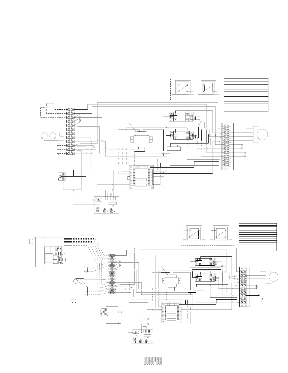
Wiring Diagrams for Revelation with Plenum
The Revelation plenum features a unique design that allows easy access to
virtually anywhere inside the unit. Access is achieved by removing either end
panel. End panels feature captive screw assemblies so no hard ware can be
lost or misplaced. Once the end panel is removed, slide the plenum housing
toward the center of the unit. Service and main te nance is made simpler due to
the accessibility provided by this unique plenum design.
Each plenum also features a ventilation system designed to maintain a suit-
able operating environment for your projector. An integrated current sensor
in the Revelation circuitry turns on the fans anytime the projector is op er at ing
and circulates fresh air through the unit. Two 4" duct fl anges are located on
the ends of the plenum for installation of duct work for di rect ing the airfl ow to
and from the unit. The input fl ange is located on the motor/drive end of the
Revelation and the exhaust is located at projector end of the revelation. If duct
work is attached to the Rev e la tion, follow guidelines in Plenum Installation
Instructions on page 6.
Plenum Operating Instructions
YW/GN
WIRING DONE BY INSTALLER
220 VAC SUPPLY
50 - 60 HZ
PROJECTOR OUTLET
(OUT)
(IN)
BE
L1
GND
N
BK
FAN
DOWN
WALL SWITCH
SPDT CENTER OFF
FAN
COM
BK
UP
BK
RD
BE
RD
14 AWG
YW/GN
BE
BE
BK
14 AWG
RD
RD
RD
RD
BK
CB1B
7
8
10
9
2
34
6
5
1
F2
F1
PCB 1
F3
YW
YW
YW
BE
RD
BK
D1
C2
YW
RD
BE
ALL WIRES 18 AWG. UNLESS OTHERWISE SPECIFIED.
RD
DOWN
BE
BE
BE
BE
RD
7
8
10
9
CB1A
1
3
42
65
BK
C1
RD
BE
BE
BE
BK
WH
BE
BE
BE
RD
RD
WH
UP
BE
RD
BE
CR 2
CR 1
BK
RD
BK
BE
RD
BE
BE
BK
YW/GN
RD
DOWN LIMIT SW
UP LIMIT SW
1
8
7
56
4
3
2
BE
BE
RD
RD
WH
MOTOR
10
9
TB 2
YW/GN
BK
BE
RD
3
14 AWG
4 TURNS
I
I
CS 1
t
1 2
I
4 5
RD
14 AWG
WH
BE
11
12
10
8
9
7
5
6
4
3
2
1
SEE T1 WIRING DIAGRAM
T 1
SECONDARY SIDE
PRIMARY SIDE
T1 WIRING
BE
BK
2
1
4
RD
3
YL
BK
7
8
5
6
YL
14 AWG
TB 1
BK
SYM
C2
CR1
CS1
F2
CR2
F3
FAN
MOTOR
T1
F1
D1
C1
Fuse 1Amp AGC 250 Vac
220V .03hp 50-60hz. 200Lb-in. 1.1rpm
Transform 220V/12V@1Amp 50/60Hz
220Vac 8Watt 50cfm 1600rpm
Relay, Coil-12Vac, 2PDT 230Vac 10Amp
Relay, Coil-12Vac, 2PDT 230Vac 10Amp
Current sensor 230Vac 2-20Amp SASC
Fuse 1Amp AGC 250 Vac
Fuse 7Amp AGC 250 Vac
Capacitor 2mfd +/- 370 Vac
Capacitor 100mfd 35 Vac
Diode NTE125002B
COMPONENT SPECIFICATIONS
RD
Single Station Control
Low Voltage Multiple Station and Remote Control
www.draperinc.com
(765) 987-7999