Vortech 1996-2000 4.3L Truck/SUV User Manual
Page 18
P/N: 4GD020-010
©2001 Vortech Engineering, LLC
All Rights Reserved. Intl. Copr. Secured
26APR01 V1.2
(4.3L V-6/S-10-(4GD))
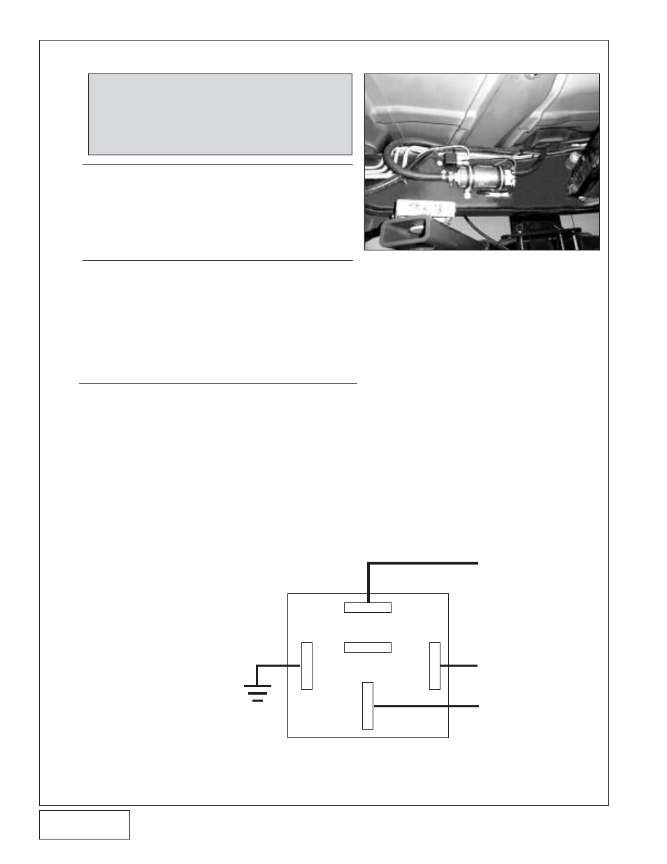
11. SUPPLEMENTARY FUEL PUMP AND HARNESS
12
QUICK DISCONNECT TYPE FITTINGS ONLY
A. Using a fuel line disconnect tool, separate the supply
line from the oulet of the fuel filter.
B. Attach the supplied 3/8" hose to the fuel filter outlet.
Connect the remaining end of the 3/8" hose to the fuel
pump inlet. Trim the hose if necessary.
COMPRESSION TYPE FITTINGS ONLY
C. Separate the factory 3/8” fuel rail supply line at the
compression fitting junction underneath the vehicle just
to the rear of the fuel filter (see
Fig. 11-b).
D. Attach the supplied 3/8” hose to 3/8" compression fitting
to the line coming from the fuel tank. Connect the
supplied length of 3/8” fuel hose to the 3/8” fitting
previously installed and the remaining end to the
supplied inline pump. Secure with a #8 hose clamp.
BOTH APPLICATIONS
E. Attach the discharge end of the fuel pump to the line
running into the fuel filter (use the supplied 5/16" hose
to 3/8" compression fitting). Position the pump in such
a way that the inlet and discharge hoses are not kinked
or restricted and maintain a gentle bend. The pump inlet
is the most critical as far as restriction is concerned
and may be trimmed if necessary to hold a smooth
radius. Make sure that all fuel pump hose connections
are secure.
F. Mount the fuel pump to the frame using the 1-1/2” adel
clamp. Position the clamp and drill a #16 hole. Secure
using a #12 hex head screw.
G. Using the existing hole in the frame
and supplied #10 hardware, mount
the relay to the vehicle frame (see
Fig.
11-a on this page and Figure 10-a on
page 11). The relay mounting hole
will also work well as a grounding
point for the pump and relay. Scrape
away the frame coating and paint to
provide a proper ground
connection. Make sure that
the pump and relay
grounding terminals are
mounted
under the relay as
opposed to
on top so that a
metal-to-metal contact will
be made.
Fig. 11-b
NOTE:
Some earlier model trucks are not equipped with
quick disconnect fittings and will require the use
of compression fittings and alternate fuel lines.
Proper lines and fittings are supplied to work with
both versions of this vehicle. Refer to the graphic
below to verify the vehicle you are modifying.
Fig. 11-a
87
86
30
85
87A
(+) FUEL PUMP
SOLID GREY WIRE
IN FUEL PUMP
HARNESS (RUNNING
ALONG THE DRIVER’S
SIDE FRAME
MEMBER)
RELAY WIRING
SCHEMATIC
(+) BATTERY LUG
GROUND