Vortech Alpha H3 Hummer - 2008 User Manual
Page 23
P/N: 4GN020-015
©2008 Vortech Engineering, LLC
All Rights Reserved, Intl. Copr. Secured
20OCT08 v2.0 08HummrH3(4GNv1.0)
17
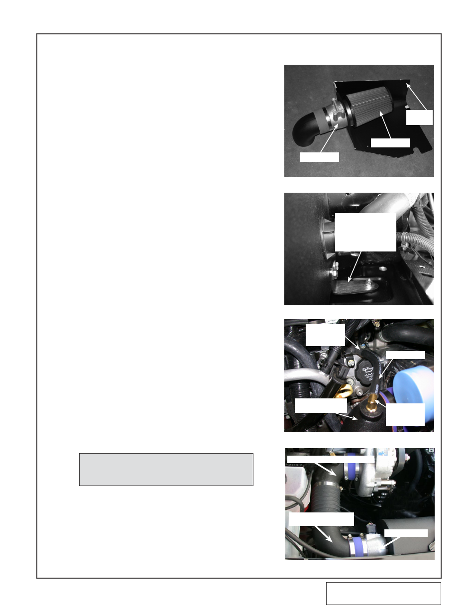
Fig. 8-a
Fig. 8-b
Fig. 8-d
8. AIR INLET INSTALLATION
MAF METER
AIR FILTER
FILTER
COVER
A.
Locate the MAF mounting hole template in
this manual. Remove and cut the template as
shown. Place the template on the passenger
side inner fender and mark the three hole
positions to be drilled. Drill the previously
marked hole locations using a 1/4" drill.
B. Install the MAF meter into the air filter cover.
Place the supplied air filter on to the meter
and secure. (See Fig. 8-a.)
C.
Install the air filter assembly into the vehicle.
Secure the MAF meter and the sound sup-
pressor shield to the previously drilled holes
in the inner fender using the 1/4-20 hardware
provided (the shield goes inside the fender
opposite the MAF) (See Figure 8-d.).
D. Secure the forward edge of the air filter hous-
ing to the front core support using the sup-
plied 90° bracket, 1/4-20 hardware and M6
Nyloc nut. (See Fig. 8-b).
E. Install the previously removed MAF electron-
ics into the supplied meter housing and
secure using the supplied hardware.
Connect the MAF electronics harness to the
MAF. (See Figure 8-d)
F.
Locate the 3.5” x 90° duct with bosses and
install the 3/8”NPT x 3/8” barb x 90° fitting.
Secure the 3.5” x 90° duct to the supercharg-
er inlet using the Ø3.5” x 2” sleeve and two
#56 hose clamps provided. Secure the 90°
duct w/out bosses to the previously installed
MAF meter using the remaining Ø3.5" x 2"
sleeve and two #56 hose clamps. (See Fig.
8-c, 8-d)
G. Connect the provided length of Ø3/8” hose to
the previously installed 3/8” barb x 90° fitting.
Insert the supplied Ø3/8” hose union into the
open end of the hose. Attach the factory 90°
molded hose to the previously installed union.
Connect the open of the 90° hose to the barb
located on the passenger side valve cover.
(See Fig. 8-c)
H.
Connect the two 90° inlet ducts using the
Ø3.5 x 10" flex hose and secure using the
remaining #52 hose clamps provided. (See
Fig. 8-d.)
I.
Cut a piece of the supplied Ø1.0” rubber hose
approximately 4” long and secure it to the
Ø1” port on the previously installed CAC
using the #16 hose clamp provided.
FACTORY
MOLDED
90°
Ø3/8" HOSE
Ø3.5" X 90°
DUCT
3/8" NPT X
3/8" BARB
90°
3.5” 90° ELBOW w/ BOSSES
MAF METER
3.5” 90° ELBOW w/o
BOSSES
Fig. 8-c
SUPPORT
BRACKET
NOTE: Trim the 3/8" hose to the best fit.
Retain the extra hose to use in a
later step.