Vortech Alpha H3 Hummer - 2008 User Manual
Page 12
P/N: 4GN020-015
©2008 Vortech Engineering, LLC
All Rights Reserved, Intl. Copr. Secured
20OCT08 v2.0 08HummrH3(4GNv1.0)
6
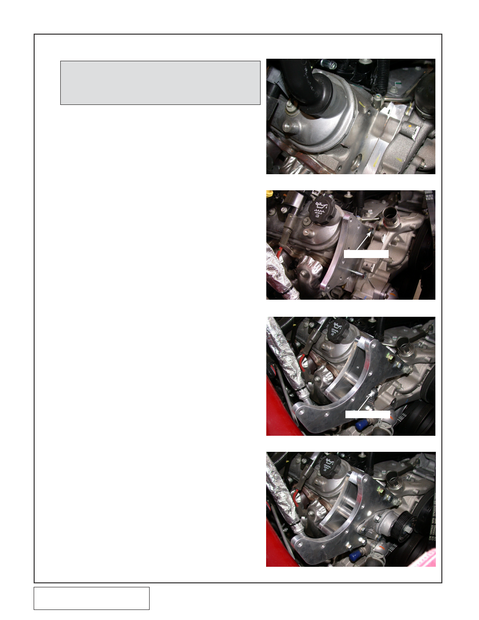
Fig. 5-b
Fig. 5-c
Fig. 5-d
A.
Locate the supercharger mounting bracket
assembly (4GN111-051)
B.
Clearance (grind) the end of the passenger
side valve cover flush with the head surface.
(See Fig. 5-a)
C.
Install the support bracket to the passenger
side cylinder head using the M10 X 25mm
screw and washer. Make sure the head sur-
face is clean and no wires or hoses are
between the bracket and mounting surface.
Loosely install one of the factory tensioner
mounting retainers in the lower cylinder head
hole location as a guild. Tighten the previous-
ly installed M10 screw. Remove the tensioner
retainer used as a guild. (See Fig. 5-b)
D.
Using two 3/8-16 x 4” screws and the lower
bracket spacer, loosely install the supercharg-
er mounting bracket.
E.
Install one of the Ø1.0” x 2.992” spacer using
the M10 x 110mm screw, do not use a wash-
er when installing this fastener as tensioner
bracket interference will result. (See Fig. 5-c)
F.
Using a one of the factory tensioner retainers,
M10 x 120mm, and 3/8-16 x 4” retainers and
washers install the upper (three hole) spacer
between the supercharger bracket and the
previously installed support bracket. Tighten
all hardware installed to this point. (See Fig.
5-c)
G. Locate the factory spring tensioner and sup-
plied mounting hardware: Place the 0.121”
thick washer onto the M10 x 130mm screw
and insert it through the factory spring ten-
sioner. Insert the 3/8-16 x 4.25” screw and
washer through the tensioner. Place the two
Ø.875” x 1.98” spacers on the previously
installed hardware. Insert the 3/8-16 x .75”
screw and washer through the remaining ten-
sioner hole and place the .025” spacer on it.
Carefully install this assembly. The M10
screw will go through the support bracket and
into the head. The 3/8-16 x 4.25” screw
secures to the support bracket. And the 3/8-
16 x .75” screw secure to the supercharger
mounting bracket. (See Fig. 5-d, 5-l, 5-m)
NOTE: For the following section, refer to Fig 5-l &
Fig. 5-m on page 10 and 11, for screw and
spacer location. Do not tighten until
instructed to.
5. MOUNTING BRACKET AND SUPERCHARGER INSTALLATION
M10 x 25mm
M10 x 110mm
Fig. 5-a