Vortech 2006-2010 6.1L Hemi Cars (Charger, Challenger, Magnum, 300C) User Manual
Page 26
P/N: 4CL020-010 v6.0, 02/28/2012
©2012 Vortech Engineering, Inc.
All Rights Reserved, Intl. Copr. Secured
12
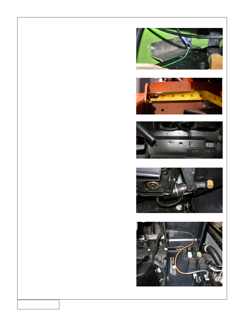
Fig. 8-d
Fig. 8-a
8.
RESERVOIR AND WATER PUMP ASSEMBLY AND INSTALLATION
Fig. 8-b
1. Attach the water reservoir bracket to the reservoir
using ¼-20 x .5” cap screws. (See Fig. 8-a for
bracket orientation).
2. In the area in front of the driver side front wheel,
position the water reservoir/bracket next to the
frame rail. Orient the assembly for best clearance,
at least 6” from the rear face of the bumper (See
Fig. 8-b)
3. Mark mounting bracket location and remove. Drill
two 11/64” holes for the supplied #12 sheet metal
screws (See Fig. 8-c).
4. Using thread sealant, install the 1/2” NPT 90° hose
barb fitting into the top and bottom of the supplied
plastic reservoir.
5. Secure the assembly to the frame rail using two #12
sheet metal screws.
6. Trial fit the front bumper cover to verify water res-
ervoir clearance.
7. Cut off the electrical plug on the water pump leaving
as much wire connected to the pump as possible.
Install the supplied ¼” eyelet on the water pump
ground wire (brown wire).
8. Connect the pump inlet to the bottom reservoir fitting
with a piece of the supplied hose. Point pump to
discharge up at a 45° angle for 300C vehicles, or
forward (and slightly up, to allow air to escape the
pump housing) for all other vehicles. Secure hose
with clamps on both ends. Drill a hole in the radia-
tor support and secure the water pump to it using
an adel clamp and #12 sheet metal screw. Make
sure to ground the fuel pump under the mounting
screw. (See Fig. 8-d)
9. Connect a hose to the top of the reservoir and run
it up to the area next to the driver side valve cover.
This hose will later be connected to the 90 degree
fitting installed in the bottom of the supplied surge
tank (trim for ideal routing).
10. Drill a 5/8 hole in rear facing side of the power dis-
tribution box lid approx. 3 inches from inner edge.
Insert supplied grommet into hole. Install supplied
fuse holder from inside of lid, pressing one end into
the grommet. Connect fuse tap and slide connector
to fuel pump fuse referring to the owner’s manual.
Connect remaining end of fuse holder to water
pump wire using supplied wire. Route wire behind
engine following the factory loom. Install supplied
split loom over wire (See Fig. 8-e).
Fig. 8-c
Fig. 8-e