Fm - continued: modulation index, Tipt p, Fm modulation index – Tiptop Z3000 Smzrt VCO MKII User Manual
Page 14
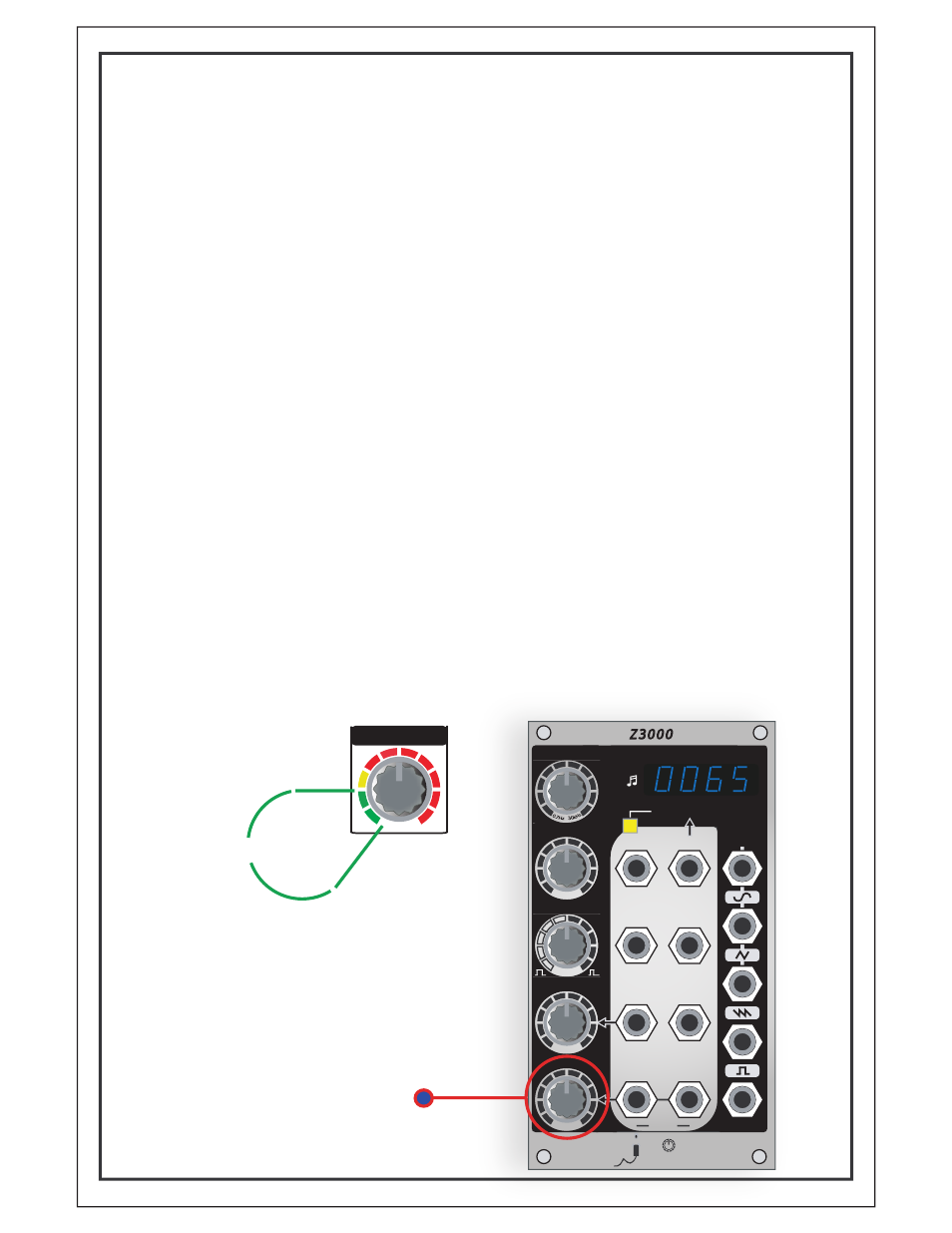
FM - Continued: Modulation Index
The amount of modulation applied to the second
oscillator is commonly known as the modulation
index. The modulation index is controlled by the FM
knob on the Z3000mkII.
It is difficult to calculate the actual spectrum of the
resulting sound created by the modulation index, but
the more modulation applied, the more complex the
sound gets, resulting in noise and frequency drift.
For example, increasing the modulation index of a sine
wave modulating another sine wave, the resulting
waveform changes from a sine wave at modulation
index 0 (FM knob to MIN), through increasingly more
complex waveforms, ending with noise at a very high
modulation index. The change from sound to noise
can be quite sudden, so it should be noted that a
small amount of modulation can provide more
desirable results. (Continued...)
FM Modulation Index
MIN
MAX
FM
‘Safe Zone’
MIN
MAX
MIN
MAX
LOW
HIGH
SYNC
HSM
1V/Oct
1V/Oct
Linear FM
INPUT
PWM
FM 1
LOW
HIGH
Hz
Oct
FM 2
INPUT
CV IN
INPUT
CV IN
CV OUT
INPUT
INPUT
+
+
+
FREQUENCY/NOTE/OCTAVE
Tipt p
A u d i o
Z 3 0 0 0
Smart VC-Oscillator
FREQUENCY
FINE TUNE
PULSE WIDTH
PWM
FM
SYNC
HSM
1V/Oct
EXT-IN
Linear FM
INPUT
PWM
FM 1
FM 2
CV IN
INPUT
CV IN
INPUT
INPUT
INPUT
+
+
+
+
Tipt p
A u d i o
Z 3 0 0 0
Hz
Oct
FREQUENCY/NOTE/OCTAVE
FM
PWM
PULSE WIDTH
FINE TUNE
MAX
MIN
MIN
MAX
LOW
HIGH
LOW
SHAPER
WAVE
FREQUENCY
Smart VC-Oscillator
HIGH