3 auxiliary relay contacts, 4 led indicators – SurgeX CM-1120-RT24 User Manual
Page 7
Space Saver Manual
7
3.3.3 Auxiliary Relay Contacts
The auxiliary relay contacts, Pins 6 & 7, provide a way to cascade units or to provide
confirmation feedback to a central controller. When the switched receptacles are on, the aux
relay contacts are closed. There is a 1 second delay before the aux relay closes, which allows
time for the SurgeX Inrush Current Elimination (ICE™) circuit to operate. This short delay in
combination with the SurgeX ICE™ makes it unnecessary to sequence the power to several large
loads (such as amplifiers) because of inrush current. SurgeX Space Saver products, when
cascaded, can turn on a bank of large amplifiers with no inrush current, and therefore no risk of
tripping a circuit breaker.
To cascade two or more Space Saver products, connect the aux relay contacts of one unit to the
contact closure input of the next unit. To provide confirmation feedback, connect the aux relay
contacts to an input on the central controller.
The relay contacts are rated for 1 amp at 30 V DC.
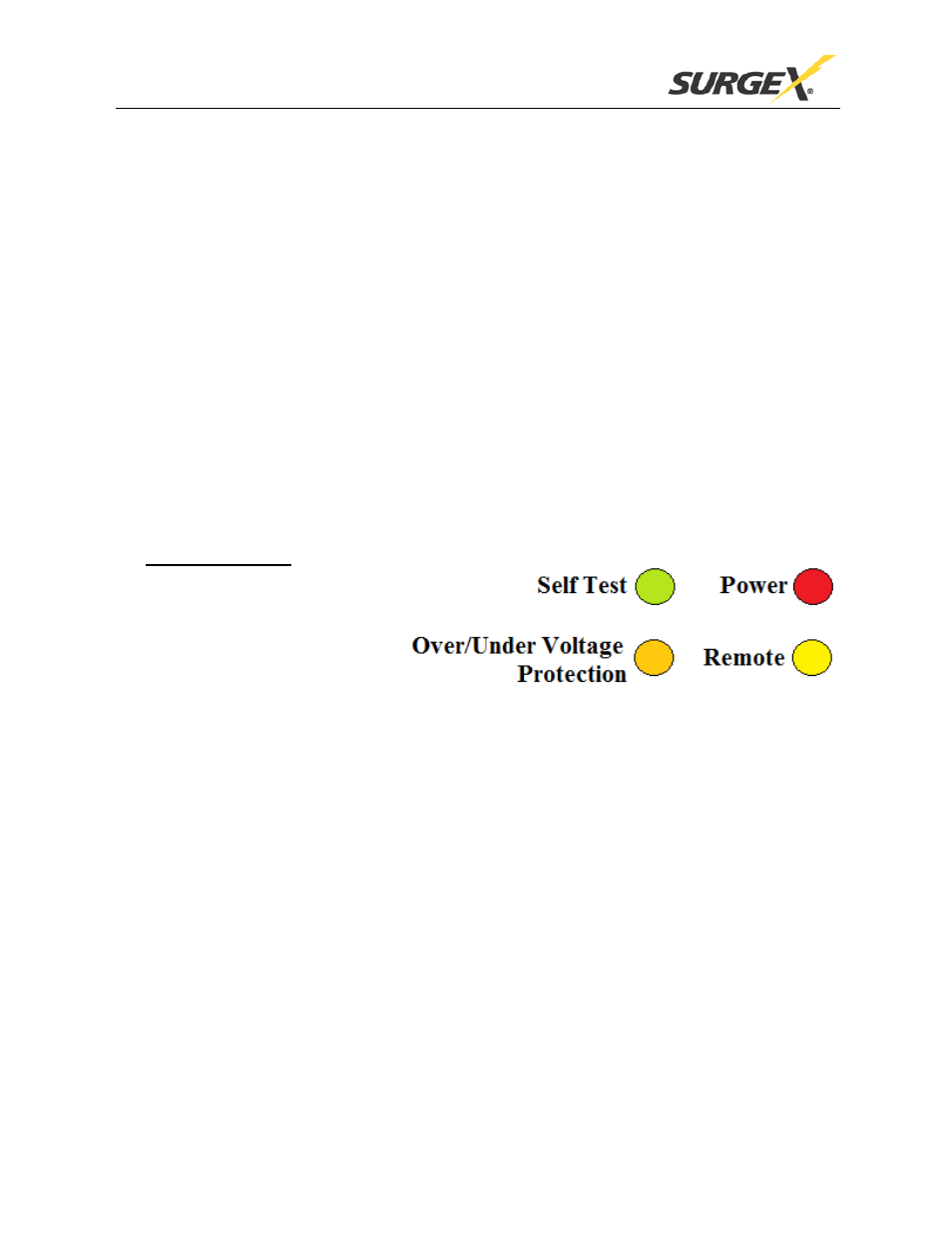
4
LED Indicators
There are four LED indicators
located on the front panel. Their
function is as follows:
Self Test (Green):
When illuminated, the surge protection circuitry is
functioning correctly.
Power (Red):
When illuminated, the power switch is turned on, power is
applied to the unit, and the AC voltage is within normal
limits.
Over/Under Voltage
When illuminated, indicates that the AC voltage is either
Protection (Orange):
below 90V or above 145V.
Remote (Yellow):
When illuminated, indicates that the remote control is
active and the rear switched receptacles are on.