3 remote control connections, 1 control inputs, 2 external led connections – SurgeX CM-1120-RT24 User Manual
Page 6
Space Saver Manual
6
3.3 Remote Control Connections
Remote control connections are wired to the green 7-pin plug-in Phoenix terminal block on the
rear of the unit next to the power cord. The terminal block is shipped with a jumper wire between
pins 1 & 2 so that the unit can be used without a remote control connection. If you will be using
remote control you will first need to remove this jumper wire. You can unplug the terminal block
to make connections and after you have made the connections to the terminal block, plug it back
into the connector on the rear of the unit. Never solder (tin) wires before inserting into a terminal
block – solder cold flows and you will eventually have loose connections!
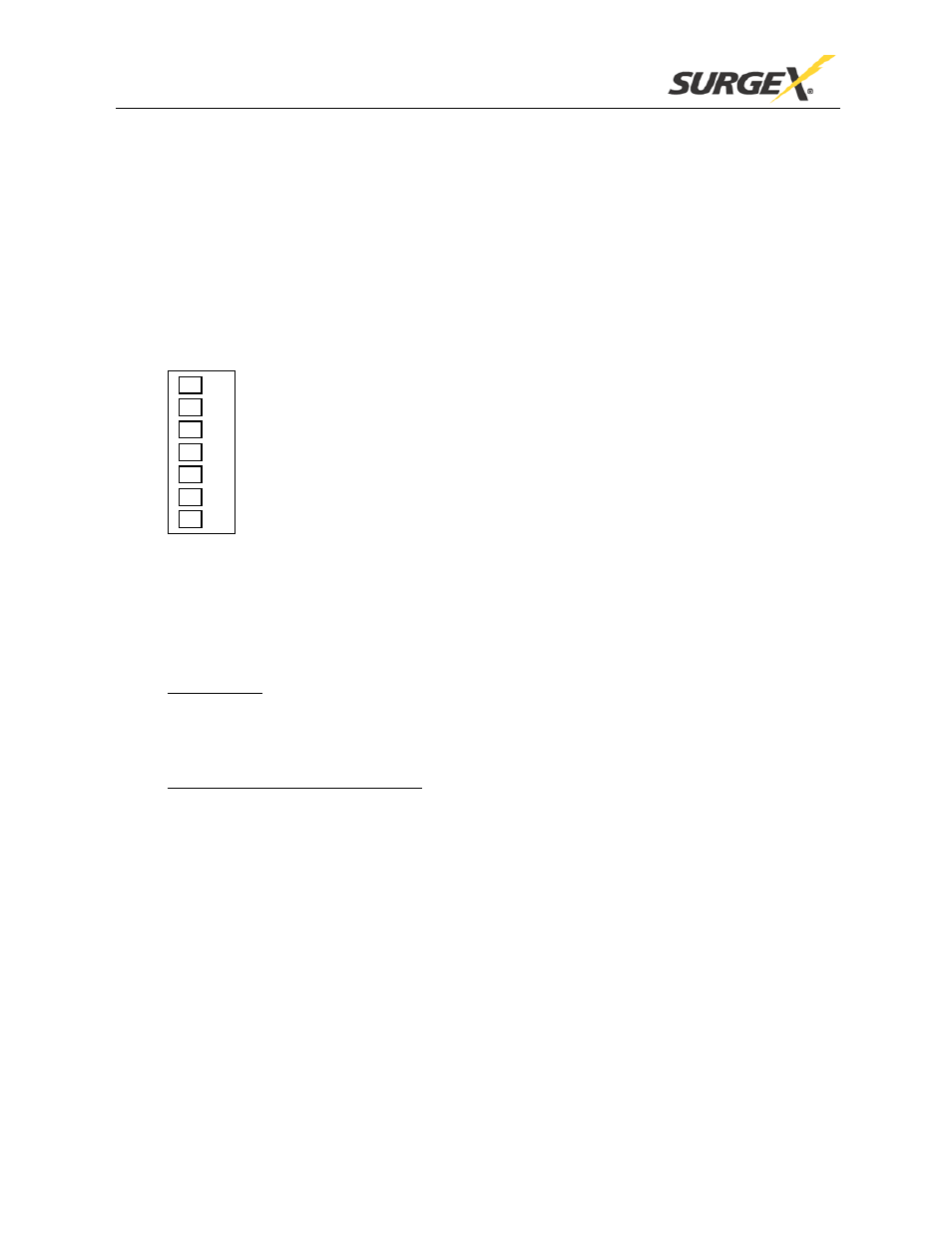
The connections are shown below:
3.3.1 Control Inputs
The Space Saver products can be controlled by a DC voltage in the range 5V to 30V, by a
contact closure (such as a relay), by a switch (latching), or by another SurgeX product such as
the SEQ. Switches with gold contacts are recommended for the best long-term reliability.
a) DC Voltage:
b)
The unit will power up when the voltage is present, and power down when
there is no voltage. Connect the positive wire to Pin 2 (Applied Voltage +), and the
negative wire to Pin 3 (Applied Voltage -). The positive and negative connections must
be made with the correct polarity for proper operation.
Contact Closure/Latching Switch:
3.3.2 External LED Connections
The unit will power up when the contacts are closed,
and power down when the contacts are open. Connect the two wires from the contacts or
switch to Pin 1 (Contact Closure) and Pin 2 (Contact Closure / Applied Voltage +).
The CM and VM Space Saver products are able to drive external LEDs or other signaling
devices through their 12V DC output, which can provide up to 10mA of current. External LEDs
connected in this way will be On when the unit’s AC receptacles are On, and Off when they are
Off. When connecting LEDs to the 12V output, a series resistor is required. For example, many
LEDs work well with 10mA of current, so a 1K
Ω resistor is usually a good choice. If more than
one LED is required, then use a separate series resistor for each LED. For example, two external
LEDs, each with a 2k
Ω series resistor, could be powered from one unit at 5mA each.
Connect each LED anode to “Remote LED +” through a resistor, and the cathodes to “Remote
LED -”.
Pin 1 – Contact Closure
Pin 2 – Contact Closure / Applied Voltage +
Pin 3 – Applied Voltage -
Pin 4 – Remote LED +
Pin 5 – Remote LED -
Pin 6 – Aux Relay Contact
Pin 7 – Aux Relay Contact