Figure 8: 16-bit scsi id cable connection – StorCase Technology DS60 User Manual
Page 10
DS60 Installation Instructions - Rev. C02
StorCase Technology, Inc.
Installation
7
2mm ID Select Cable from
Data Stacker ID Select Switch
Orange (ID3)
Signal Row
GND Row
Black (ID0)
Brown (ID1)
Red (ID2)
Figure 8: 16-Bit SCSI ID Cable Connection
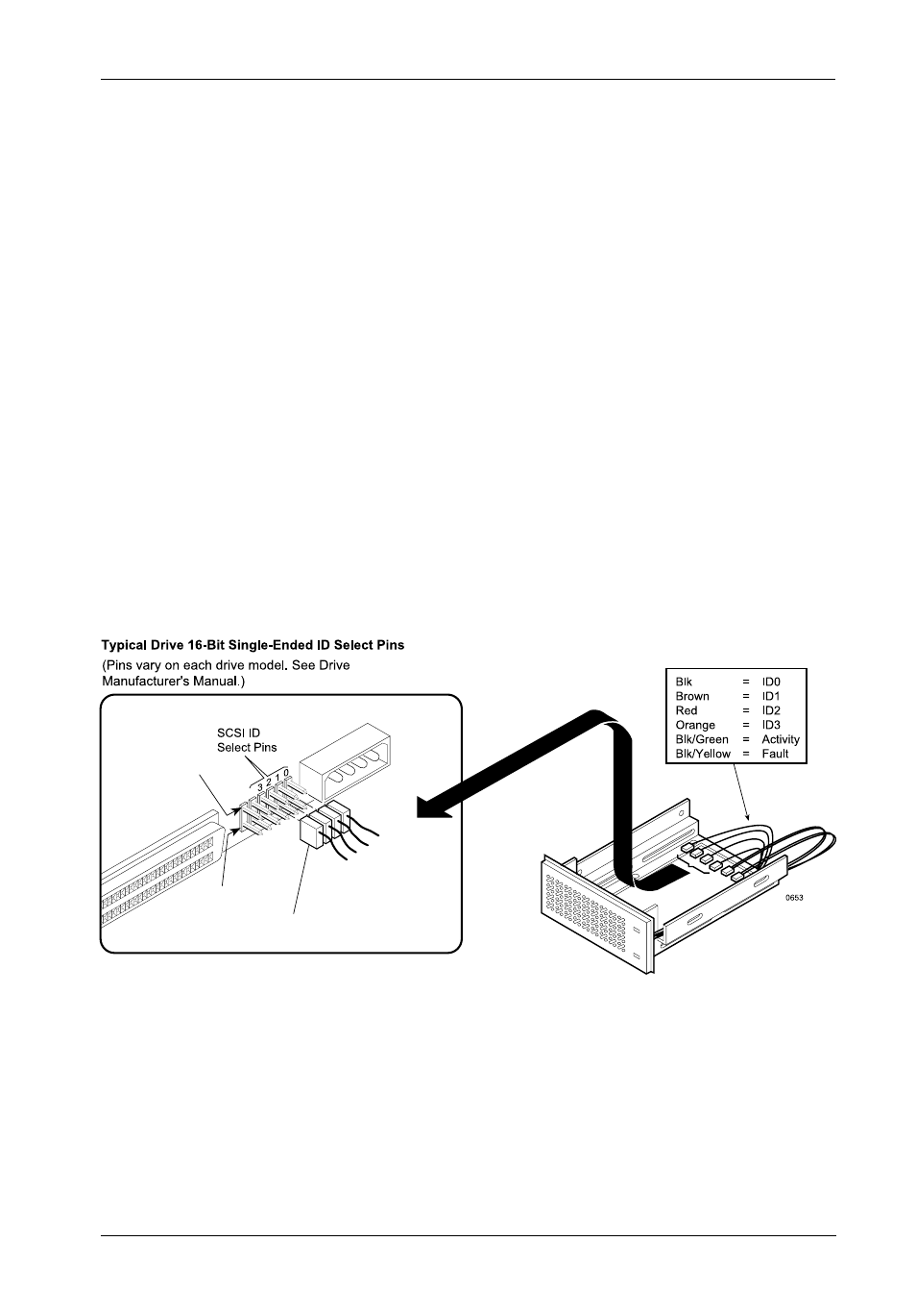
IF INSTALLING A 16-BIT SCSI DEVICE:
The SCSI ID cable contains black, brown, red, and orange wires. Attach four (4)
connectors from the SCSI ID select cable to the appropriate 2mm drive pins (Figure 8).
The black wire plugs into the drive pin used to select ID0, the brown wire plugs into
the drive pin for ID1, the red wire plugs into the drive pin for ID2, and the orange wire
plugs into the drive pin to select ID3.
In most cases, the drive manufacturer labels each pair of SCSI ID select pins in
significant bit order (0, 1, 2 and 3). One row of drive pins is the signal row, and one
row is designated for ground. Refer to the drive manufacturer's documentation for
specific pin configurations.
The Data Stacker ID select cable provides 2mm, 2-conductor drive connectors. A
single wire attaches to one side of each connector. The cable side of each connector
must align with the signal pin on the drive.