Receiving frame rear panel – StorCase Technology S20A124 User Manual
Page 13
6
Introduction
StorCase Technology, Inc.
S20A124 User's Guide - Rev. B01
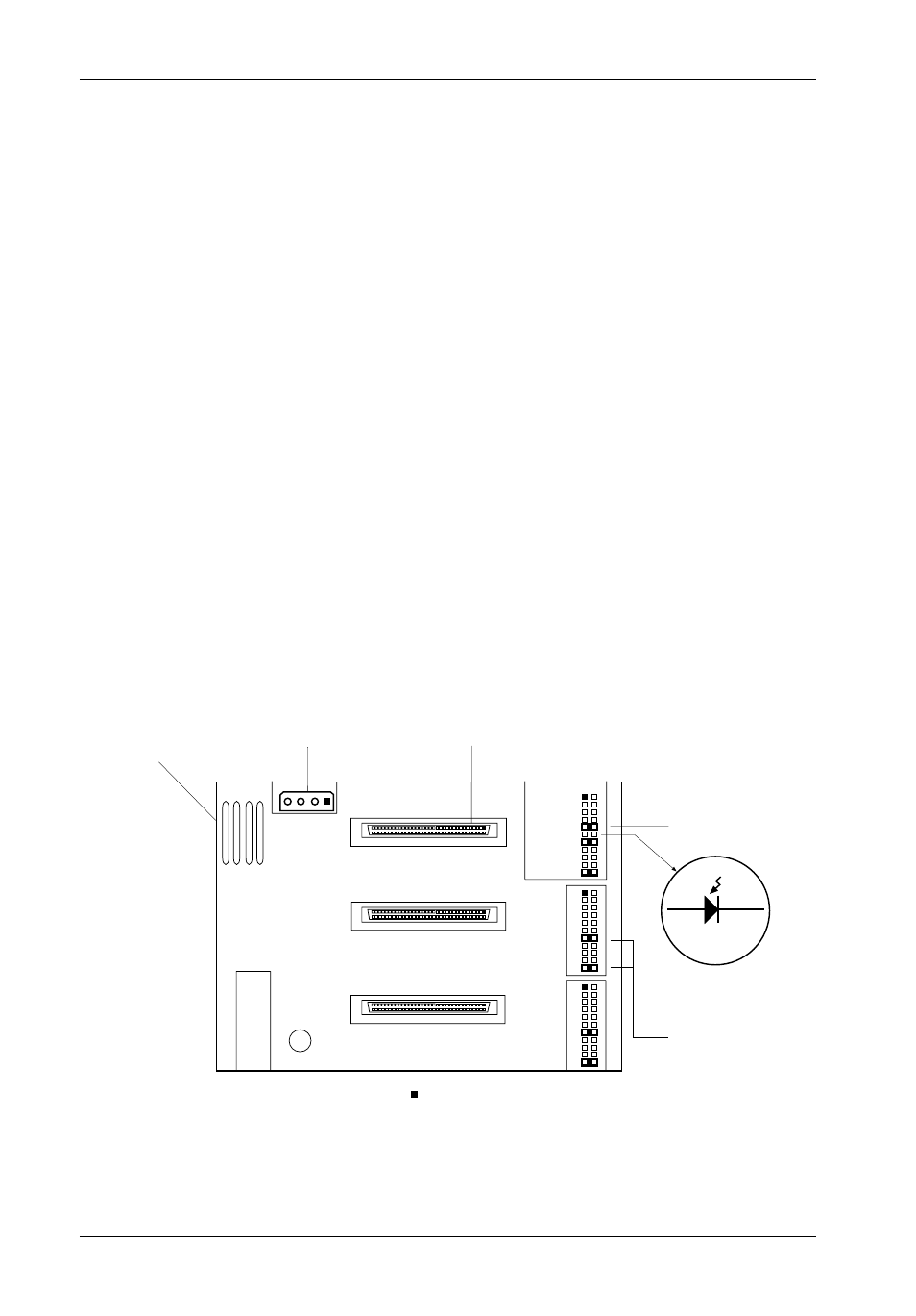
Figure 5: Receiving Frame Motherboard (Rear View)
DC Power
Connector
J3A
J3B
J3C
Cathode
Anode
P11
P12
Remote
Activity LED
Jumpers
(Factory-Installed)
68-pin SCSI
I/O Connector
= Pin 1
Drive B
Drive C
Drive A
0503d
1
21
1
21
1
21
Blower
Vent
Jumper
(Factory-Installed)
Receiving Frame Rear Panel
(Figure 5)
DC Power Connector (J1): The Data Express uses a standard 4-pin DC power connector
to accept DC power.
I/O Connectors (Drive A, Drive B, Drive C): The input/output connector provides a standard
interface for 16-bit wide SCSI signals.
Option Pins (J3A, J3B, J3C)
Remote Unit ID Selection: Pins 1-8 of these connectors are provided for remote
unit
SCSI ID selection through the computer system. Remote ID selection requires that
the
unit ID switch located on the inside of the receiving frame be set to "0" (device ID
selection
is set with a switch located on the inside of the receiving frame as shown
in Figure 9).
See Table 1 for J3 pin assignments.
Remote Activity LED: Pins 11 & 12 are used for a remote LED device activity indicator.
Jumpers: Installed at the factory - Do not remove!
Blower Vent: One (1) built-in blower provides enhanced heat dissipation (4.6 CFM).