StorCase Technology DE100i-SWU2X User Manual
Page 16
DE100i-SWU2X User's Guide - Rev. B01
StorCase Technology, Inc.
Installation
9
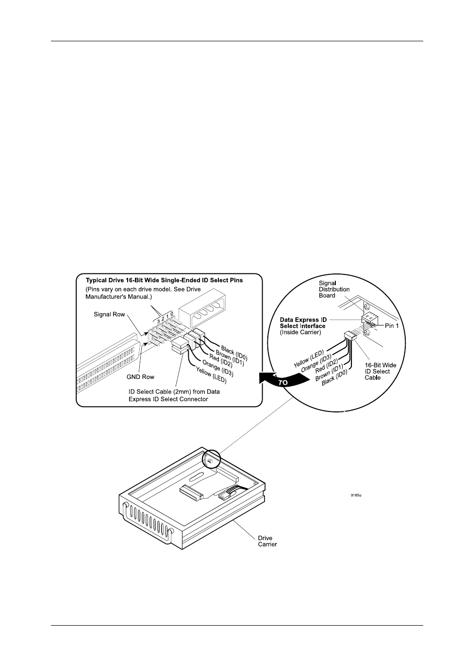
Figure 7: Typical ID Select Connections (2mm Drive Pins)
TYPICAL 2MM DRIVE ID PIN CONFIGURATION
Figure 7 illustrates a typical ID select connection to a drive with 2mm ID select pins. The wires
on the wire harness connect to the positive pin (or signal pins) on the disk drive. In some cases,
the drive manufacturer will label the signal pins as Pin 1, 3, 5, and 7 (instead of 0, 1, 2, 3 as
shown in Figure 7 below). Also, in some cases, the even-numbered Pins 2, 4, and 6 are used
for Ground.
Attach the ID select cable to the drive using the 2mm connectors. Align the ID0 pin with the
black wire. Attach the 1.25mm connector on the other end of the ID select cable to the 1.25mm
connector (J3B) provided on the signal distribution board, located inside the carrier. Refer
to the manufacturers documentation to disable termination on the drive.
- DE100i-SW (35 pages)
- DE50 (33 pages)
- DE50 (27 pages)
- DE110 (33 pages)
- DE110 (2 pages)
- DE110 (31 pages)
- DE110 (27 pages)
- DX115 (25 pages)
- DE75i-A (31 pages)
- DE75i-A66 (29 pages)
- DE75i-A100 (31 pages)
- SATA DE75 (28 pages)
- DE75i-S (31 pages)
- DE75i-SW (33 pages)
- DE75i-SWC (33 pages)
- DE75i-SW160 (29 pages)
- S20A114 (29 pages)
- DE75i-SWC160 (29 pages)
- DE90i-A (29 pages)
- DE90i-A66 (23 pages)
- DE90i-A100 (23 pages)
- DE90i-S (25 pages)
- DE100i-A (33 pages)
- DE100i-A66 (29 pages)
- DE100i-A100 (29 pages)
- DE100i-CSWTN (2 pages)
- DE100i-S (39 pages)
- DE100i-SWD (33 pages)
- DE100i-SWU2 (37 pages)
- DE100i-SWCU2 (33 pages)
- DE100i-SW160 (35 pages)
- S20A102 (33 pages)
- DE100i-SWC160 (39 pages)
- Ultra320 DE100 (31 pages)
- DE110 (27 pages)
- DE110 (31 pages)
- DE110 (29 pages)
- DE150i-SWC (33 pages)
- DE200i-S (33 pages)
- DE200i-CSWTN (2 pages)
- DE200i-SW (35 pages)
- DE200i-SWU2 (37 pages)
- DE200i-SWCU2 (35 pages)
- S20A108 (33 pages)