StorCase Technology S20A114 User Manual
Page 18
S20A114 User's Guide - Rev. A01
StorCase Technology, Inc.
Installation
11
5.
Adjust the front of the receiving frame so the carrier slides freely in and out on
the receiving frame guides. The position of adjoining peripheral units may require
adjustment.
6.
To connect a drive to a remote activity LED in the computer system or expansion
chassis, connect the appropriate cable(s) to the receiving frame motherboard option
Pins 11 and 12 as shown in Figure 5.
7.
Connect the I/O cable from the host adapter to the receiving frame. The Pin 1
indicator on the cable must be properly aligned. Refer to Figure 5 for the correct Pin
1 location.
NOTE:
No onboard termination is provided on the DE75. External termination must
be provided.
8.
Connect the power cable from the DC power supply in the computer or expansion
chassis to the power connector on the DE75 receiving frame. Refer to Figure 5 for
the DE75 receiving frame power connector location.
9.
Replace any expansion boards that may have been removed earlier. Replace the
system cover according to the manufacturers instructions.
10.
Reconnect any system or peripheral cables removed earlier.
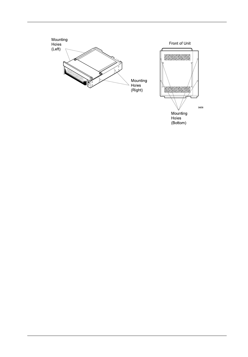
Figure 8: Receiving Frame Mounting Holes