Scsi interface connector – StorCase Technology DE75i-S User Manual
Page 23
StorCase Technology, Inc.
DE75i-S User's Guide - Rev. A01
16
Installation
Signal
Pin
Signal Pin
-DB(0)
2
Ground 30
-DB(0)
4
-ATN
32
-DB(0)
6
Ground
34
-DB(0)
8
-BSY
36
-DB(0)
10
-ACK
38
-DB(0)
12
-RST
40
-DB(0)
14
-MSG
42
-DB(0)
16
-SEL
44
-DB(0)
18
-C/D
46
Ground
20
-REQ
48
Ground
22
-I/O
50
Ground
24
TRMPWR
26
Ground
28
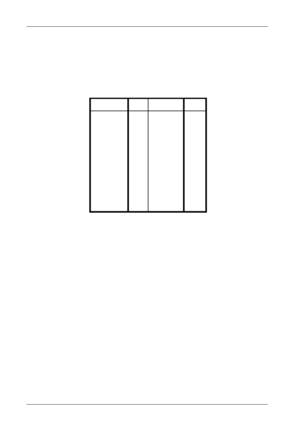
Table 2: SCSI Interface Connector Pin Assignments
SCSI Interface Connector
The SCSI interface connector pin assignments are supplied for your convenience.
NOTE:
All odd pins except Pins 23, 25, 27 and 29 are connected to ground. Pin
25 is left open.
CAUTION:
Pin 25 must not be connected to ground at the HOST end or the drive end
of the cable. If the I/O connector is accidentally plugged upside down,
terminator power on Pin 26 will be shorted to ground.
The minus (-) sign next to the signals indicates asserted state is the low
voltage of the two levels used for logic signals.
Pins 23, 27, and 29 are reserved.
- DE100i-SW (35 pages)
- DE110 (27 pages)
- DE50 (33 pages)
- DE50 (27 pages)
- DE110 (33 pages)
- DE110 (2 pages)
- DE110 (31 pages)
- DX115 (25 pages)
- DE75i-A (31 pages)
- DE75i-A66 (29 pages)
- DE75i-A100 (31 pages)
- SATA DE75 (28 pages)
- DE75i-SW (33 pages)
- DE75i-SWC (33 pages)
- DE75i-SW160 (29 pages)
- S20A114 (29 pages)
- DE75i-SWC160 (29 pages)
- DE90i-A (29 pages)
- DE90i-A66 (23 pages)
- DE90i-A100 (23 pages)
- DE90i-S (25 pages)
- DE100i-A (33 pages)
- DE100i-A66 (29 pages)
- DE100i-A100 (29 pages)
- DE100i-CSWTN (2 pages)
- DE100i-S (39 pages)
- DE100i-SWD (33 pages)
- DE100i-SWU2 (37 pages)
- DE100i-SWCU2 (33 pages)
- DE100i-SWU2X (35 pages)
- DE100i-SW160 (35 pages)
- S20A102 (33 pages)
- DE100i-SWC160 (39 pages)
- Ultra320 DE100 (31 pages)
- DE110 (29 pages)
- DE110 (27 pages)
- DE110 (31 pages)
- DE150i-SWC (33 pages)
- DE200i-S (33 pages)
- DE200i-CSWTN (2 pages)
- DE200i-SW (35 pages)
- DE200i-SWU2 (37 pages)
- DE200i-SWCU2 (35 pages)
- S20A108 (33 pages)