Receiving frame rear panel – StorCase Technology DE50 User Manual
Page 12
Introduction
5
SATA 3Gbps DE50 User's Guide - Rev. B00
StorCase Technology, Inc.
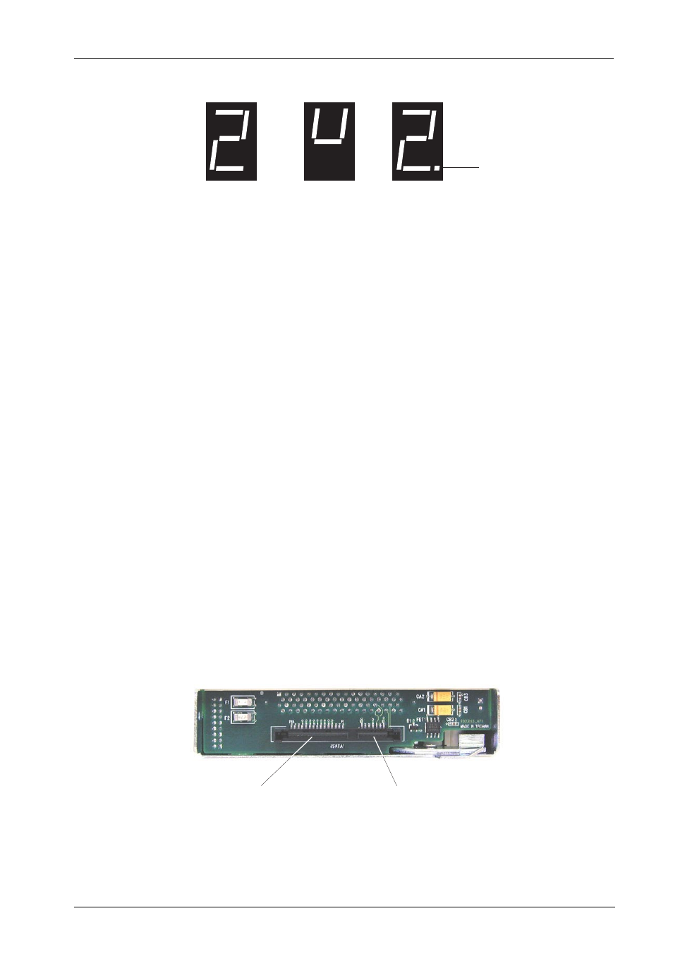
Figure 4: Receiving Frame Unit ID Number and Activity Display
Figure 5: Receiving Frame Motherboard (Rear View)
Receiving Frame Rear Panel
(Figure 5)
•
I/O Connector - The input/output connector provides a standard interface for all
SATA signals.
•
SATA Power Connector - 15-Pin SATA power connector to accept DC power.
NOTE:
If your system does not accommodate the SATA power connector,
simply use the SATA-to-DC Power adapter cable (included in the ac-
cessory bag) to connect to your system's DC power.
I/O
Connector
SATA Power
Connector
Carrier Installed
(unlocked)
Carrier Installed
(locked)
Carrier Removed
from Receiving Frame
The number "2" shown above is for illustration purposes only. It can be any
valid unit ID number. The letter "u" (above middle) will appear as illustrated.
Activity
Indicator *
* Some drives may support the Activity Indicator feature. Refer to your drive
manufacturers documentation for further information.