Spectrum Controls 1794sc-IF8IU User Manual
Page 20
2-10
Flex™ IO Isolated Universal Input Module
User's Manual Pub. 0300231‐01 Rev. A
is seated when the latching mechanism (7) is locked into the module.
6) Repeat the above steps to install the next module in its terminal base unit.
Section 2.5
Field Wiring
Connections
Wiring to the IF8IU module is made through the terminal base unit on which the module
mounts. Compatible terminal base units are:
Module 1794-TB3G
1794-TB3GS
1794sc-IF8IU Yes
Yes
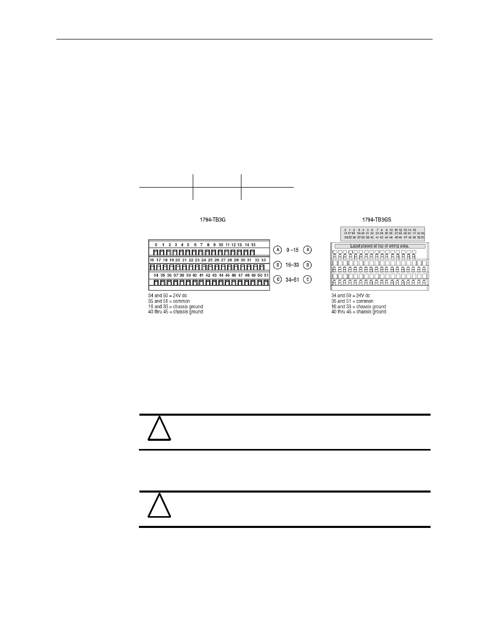
2.5.1 Field Wiring using a 1794-TB3G and TB3GS Terminal Base
1) Connect the individual signal wiring to numbered terminals on the 0–15 row (A)
and 17–32 row(B) on the terminal base unit. Connect the input devices as
shown in the wiring table on page 2-11 .
2) Terminate shields: to terminals 16 or 33 on row B, or 40 through 45 on row C.
3) Connect +24V dc to terminal 34 on the 34-51 row (C), and 24V common to
terminal 35 on the 34-51 row (C).
!
Attention
To reduce susceptibility to noise, power IF8IU modules and digital
modules from separate power supplies. Do not exceed a length of 33ft
(10m) for dc power cabling.
4) If daisy chaining the +24V dc power to the next base unit, connect a jumper
from terminal 50 (+24V) on this base unit to terminal 34 and from terminal 51
(24V dc common) to terminal 35 on the next base unit.
!
Attention
Do not daisy chain power or ground from the IF8IU terminal base unit
to any ac or dc digital module terminal base unit.