Table 4(controller operation status register), Table 5 (ccw program variables) – Spectrum Controls 2080sc-OW2IHC User Manual
Page 9
Micro800™ 2 Ch High Current Digital Output Module
12
Publication 0100188-01 Rev. A
Minimum Load
10mA at 5VDC per point.
(This value can change due to the switching frequency, environmental conditions, and desired
reliability level, therefore it is recommended to check this with the actual load.)
Initial Contact
Res. of Relay
< 5mΩ typical, 30 mΩ max
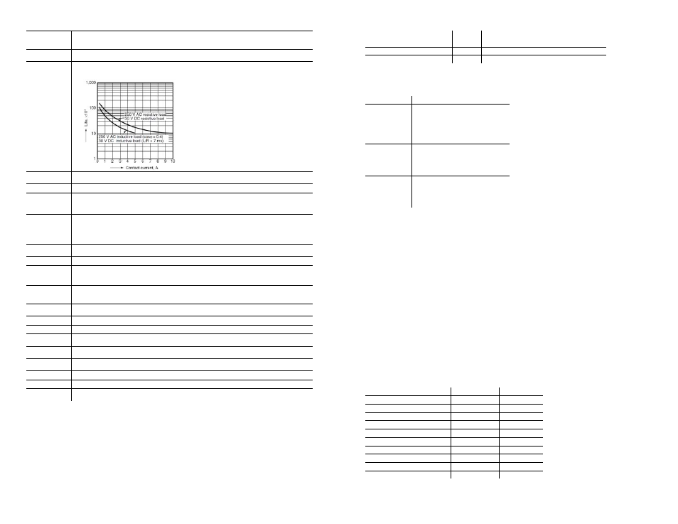
Expected Life
of
Electrical
Contacts
100k operations @ 20 times/min, at rated resistive capacity and temperature.
Switching
Frequency
Maximum 1 cycle /3s at rated load (1.5s on, 1.5s off)
Bounce Time
1.2 ms average
Maximum Off
State Leakage
1.5mA Maximum
Output Delay
Time
(From the time
the module
receives data)
10ms maximum on/off (5 ms typical) excluding bounce time
Status
Indicators
2 yellow Status Indicators (I/O)
Power source
3.3 VDC, 24 VDC from backplane
Input to
backplane
isolation
250 VAC continuous, tested at 2300VAC for 1 min.
Channel to
channel
isolation
250 VAC continuous, tested at 1500VAC for 1 minute
Power
consumption
<=35 mA at 3.3V, <=20 mA at 24V, <1.5 W
Inrush current
<120 mA at 3.3V, <120 mA at 24V
Fusing
Use external if desired
Terminal block
Wire size
#16 - #30 AWG
Terminal block
torque
0.19 Nm (1.7 lb-in)
Mounting
torque
0.2 Nm (1.48 lb-in)
Manufacturing RoHS
compliant
Dimensions
58.4mm x 29.3mm x 25mm
Status
Indicators
Individual OFF/ON Status for each I/O point
Micro800™ 2 Ch High Current Digital Output Module
9
Publication 0100188-01 Rev. A
Parameter
Offset
(Dec) Comments
MOD_MODE_CONTROL
17
Module Mode Control Register
OUTPUT_DATA 64 Output
Data
Register
Table 4(Controller Operation Status Register)
Bit Number
Description
0-3
Controller Error info:
0x00: no Error;
0x01: Operation Error;
0x02: Fatal Error
0x03-0x0F: reserved ;
4-5 Controller
mode:
0x00: non-RUN mode;
0x01: RUN mode;
0x02-0x03 : reserved ;
6-7
Controller Power info:
0x00: Power O.K.;
0x01: power failure triggered;
0x02-0x03: reserved
The following sample program, written in structured text, demonstrates
how to configure the module in CCW.
u800Slot := 1; (* Slot number for module. *)
(* This section of code is to handle the controller with Firmware earlier than rev 1.13 *)
SYS_INFO_FW(True);
IF (SYS_INFO_FW.Sts.OSMajRev = 1 and SYS_INFO_FW.Sts.OSMinRev <=12) THEN
IF SYS_INFO_FW.Sts.MajErrCode = 0 THEN
ControllerStatus[1] := 2#00010000;
WriteControllerStatus(True,u800Slot,11,1,ControllerStatus);
END_IF;
END_IF;
RunMode[1] := 16#A5;
(* Initialize RunMode register *)
WriteModModeControl(true,u800Slot,17,1,RunMode); (* Write A5 Hex to MOD_MODE_CONTROL for run mode*)
ReadModStatus(true,u800Slot,16,1,OW2IHC_S1_ModStatus);
(* Read general module status *)
WriteOutputs(True,u800Slot,64,1,OW2IHC_S1_Outputs); (* Write Output states *)
Table 5 (CCW Program Variables)
Variable Name
Data Type
Dimension
U800Slot UINT
NA
SYS_INFO_FW SYS_INFO
NA
ControllerStatus USINT
[1..1]
WriteControllerStatus Plugin_Write
NA
WriteModModeControl Plugin_Write
NA
RunMode USINT
[1..1]
ReadModStatus Plugin_Read
NA
OW2IHC_S1_ModStatus USINT
[1..1]
WriteOutputs Plugin_Write
NA
OW2IHC_S1_Outputs USINT
[1..1]