Wire the module, Configuring the module, Module input data – Spectrum Controls 2080sc-OW2IHC User Manual
Page 7
Micro800™ 2 Ch High Current Digital Output Module
14
Publication 0100188-01 Rev. A
Environmental Tests
Industry Standards
Test Level Limits
EFT/B immunity
IEC 61000-4-4*
Signal Ports:
± 3 kV @ 5 kHz for 5 minutes
Power Ports:
± 2 kV @ 5 kHz for 5 minutes
Surge transient immunity
(Performance Criteria B)
IEC 61000-4-5
Signal Ports:
± 2 kV line-earth
Power Ports
± 2kV CM
± 1kV DM
Conducted RF immunity
(Performance Criteria A)
IEC 61000-4-6
10V rms with 1 kHz sine wave
80%AM from 150 kHz…80 MHz
on signal and power ports
Magnetic Field
(Performance Criteria A)
IEC 61000-4-8
30Arms/m
AC Mains Voltage Dips,
Interruptions and Variations
IEC 61000-4-11
Standard
Safety Tests
Industry Standards
Test Level
Limits
UL Safety
UL 508 Industrial Control Equipment Seventeenth
Edition Dated January 28 1999, with revisions
through July 11, 2005 (ANSI/UL 508-
2005) (NRAQ, NRAQ7)
cUL CSA C22.2 No. 142 -M1987 Process Control
Equipment May 1987
As required
UL Hazardous Locations
ULH ANSI/ISA–12.12.01–2007 Nonincendive
Electrical Equipment for Use in Class I, Division 2
Hazardous (Classified) Locations
cULH CSA C22.2 No. 213-M1987 - Non-
incendive Electrical Equipment for use in Class I
Division 2 Hazardous Locations - March 1987
As required
CE Low Voltage Directive
IEC 61131-2 Programmable Controllers Part 2:
Equipment Requirements and Tests; Second
Edition 2003-02, Section 11-14
As required
Micro800™ 2 Ch High Current Digital Output Module
7
Publication 0100188-01 Rev. A
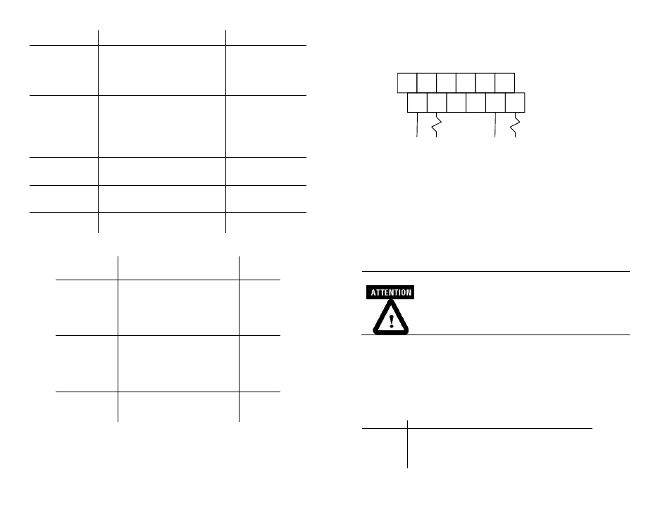
Wire the Module
Follow the wiring diagrams below to wire the module.
Note: In the diagram above, terminals with the same label are internally shorted together.
Example, CM0 (Top Row) and CM0 (Bottom Row) are internally shorted together.
Configuring the Module
The 2080sc-OW2IHC doesn’t really require configuration. It only needs
to be placed into run mode. Write a value of 165 decimal to memory
location 17 (MOD_MODE_CONTROL). See Table 3 for more
information.
Micro 800 controllers running OS firmware
revision 1.12 or older, require a decimal value of
16 be written to memory location 11
(CONTR_OPS_STATUS) before the module will
go into run mode. See program sample on
page 9.
Module Input Data
General module status can be read from memory location 16. Refer to
table below for possible responses.
Table 1 (General Module Status)
Bit Number
Description
0-1
These 2 bits define module operation mode,
0: Idle: Module is ready to RUN, and I/O is off.
1: RUN: Module is under RUN, and I/O is on.
2: Error: Error happens, and I/O is off.
3: Busy: Module is busy, cannot go to RUN, and I/O is off.
CM0
O-0
NC
NC
CM1
O-1
CM0
O-0
NC
NC
CM1
O-1
L2
or
-DC
L2
or
-DC
L1
or
+DC
L1
or
+DC
Load
Load