RTA Products RTA-B005 User Manual
Page 8
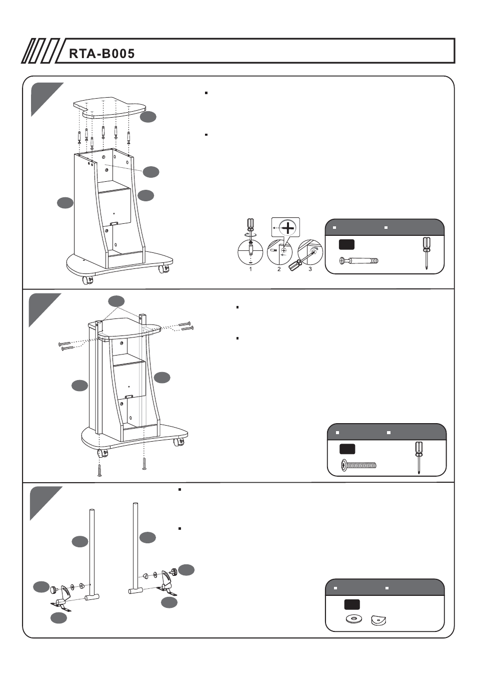
1
2
4
6PCS
6X40 MM
D
8
7
Screw Bolts (D) to the inside face of the Top Panel (8) .
Then insert the Bolts into the holes of the Back, Left
and Right Panels (4,1,2). Finally tighten the cam locks
in the Back Panel (4) and the Left & Right Panel (1&2).
Atornille los pernos (D) en la superficie interior del panel
superior (8) . Luego insérte los pernos en los huecos de los
paneles posterior, izquierdo y derecho (4,1 y 2).
Finalmente, asegure los pernos girando los cerrojos en los
paneles posterior (4) y los paneles izquierdo y derecho (1 y 2).
SCREWS
TORNILLOS
6PCS
6X35 MM
C
1
2
9
8
Use Screws (C) to fix both Lateral Structures (9)
to the Bottom Panel (7) and to the Left & Right
Panels (1&2).
Use Tornillos C para Fijar ambas Estructuras
Laterales (9) a los Paneles Izquierdo y Derecho
(1 y 2) y luego al Panel Inferior (7).
SCREWS
TORNILLOS
10
10
13
14
16
16
I
2PCS
Φ25X15MM
9
SCREWS
TORNILLOS
Place the Washers (I) between the Right Tilting Mechanism (13)
and the Top Structure (10) as shown in the drawing, then use the
Screw Knob (16) to assemble them together. Repeat the same
procedure with the Left Tilting Mechanism (14).
Coloque las Arandelas (I) entre el mecanismo de giro derecho (13)
y la estructura superior (10) seg n el dibujo, luego use el tornillo de
ajuste (16) para que queden ensamblados juntos. Haga lo mismo para
el mecanismo de giro izquierdo (14).
ú
P.8